What is a VLAN (part 6)

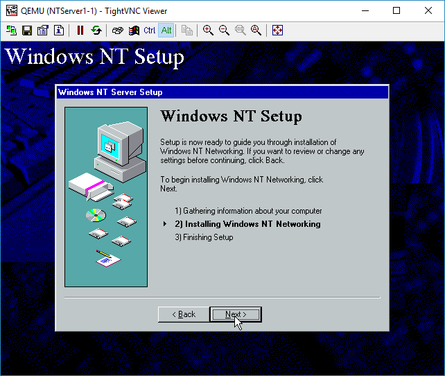
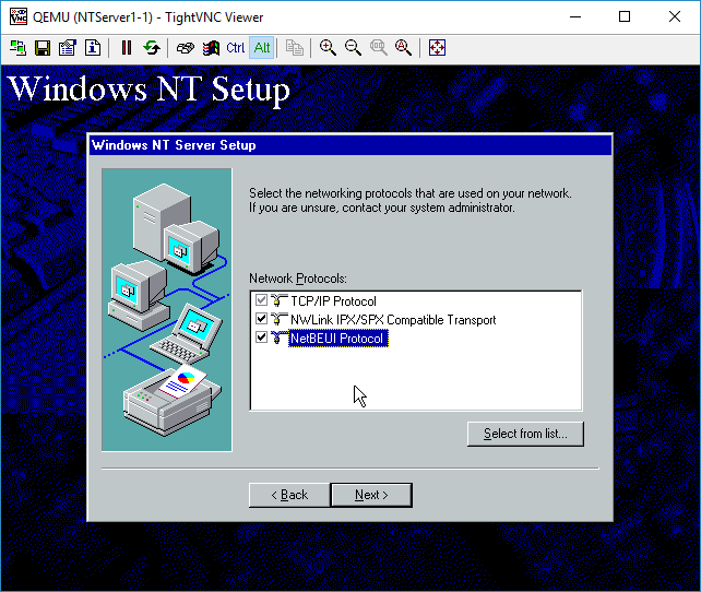
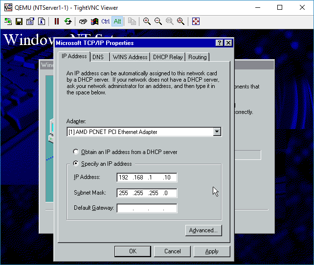
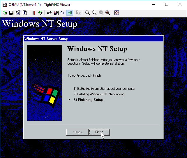
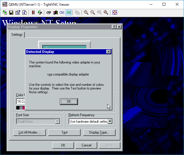
WIth Windows NT installed, it’s time to look at it on the network side.

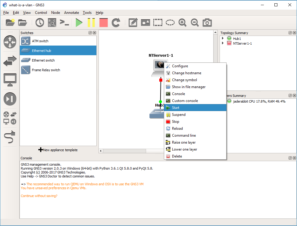
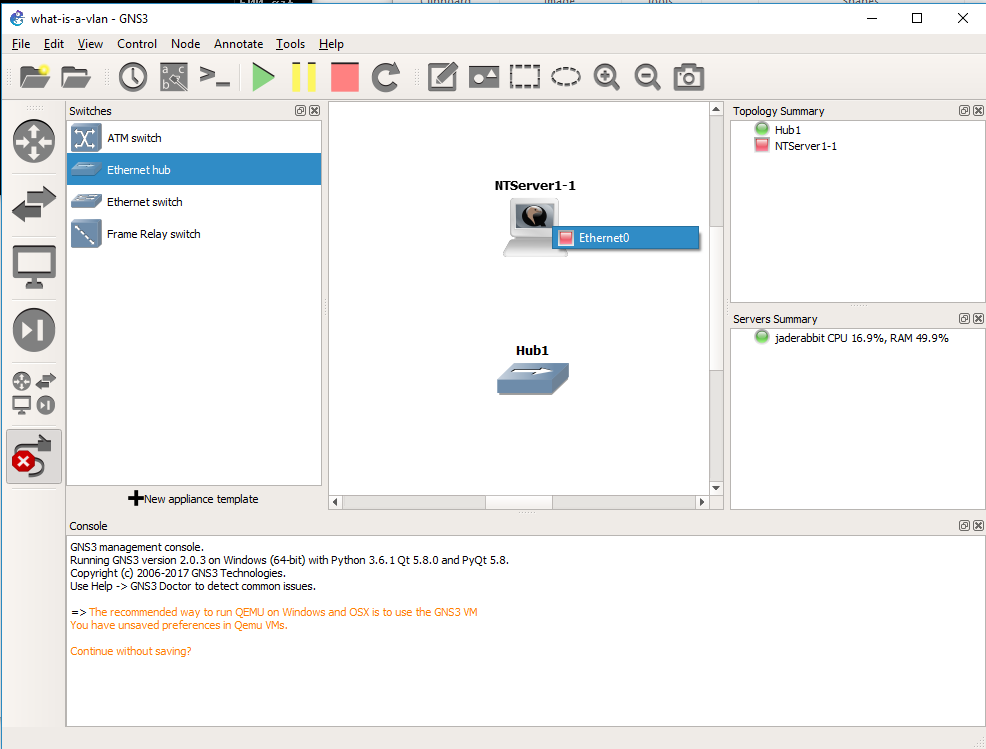
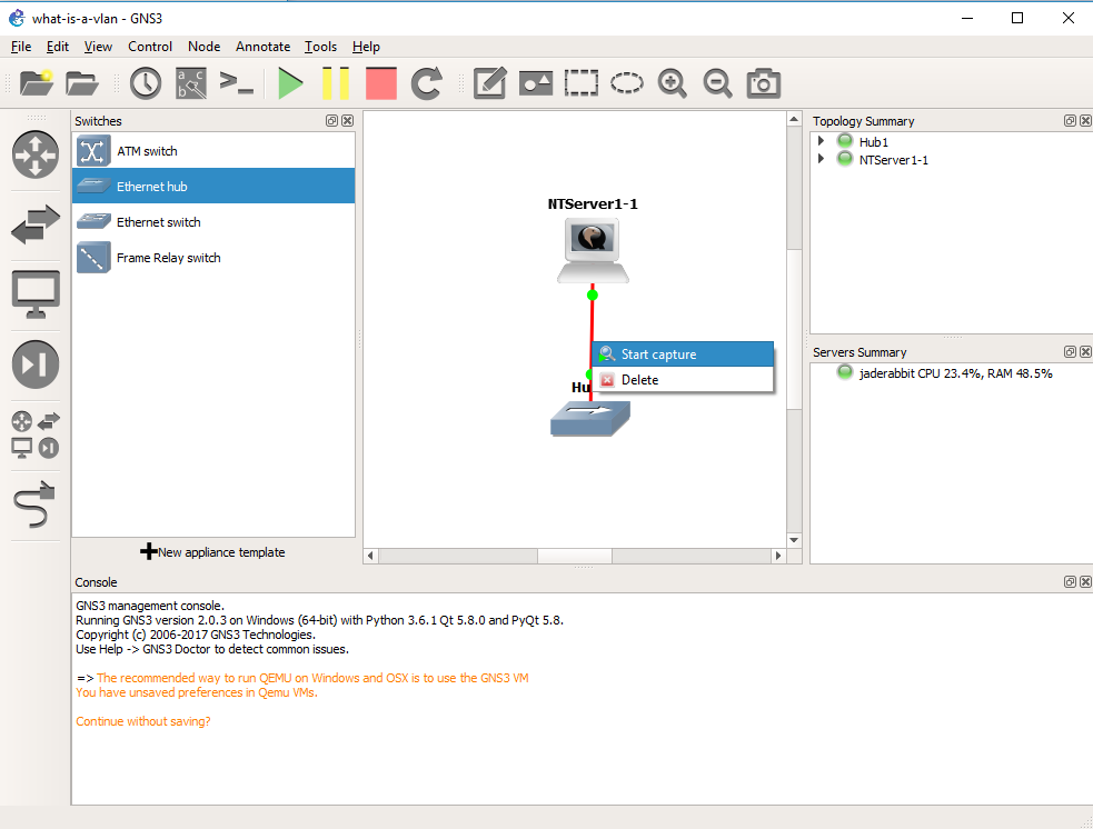
The killer feature of GNS3 is that we can inspect traffic everywhere we draw a connection.  So simply right click on the connection from the Qemu VM to the Hub, and you can start a packet capture.

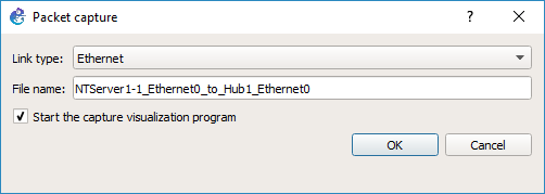
GNS3 will then prompt what the link type media is, in this case it’s Ethernet, and what the link name is.  After hitting OK, it’ll then start WireShark on the virtual link.

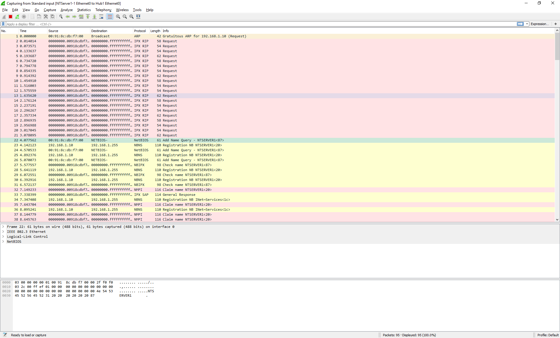
And in no time we can see the NT machine broadcasting on the network.  OK everything is looking fine.

As you can see our packet is an 802.3 Ethernet packet, with a LLC header, and a NetBIOS packet.  This is what we are expecting as the connection to the hub is ‘raw’.

Now that we have verified that we can connect to the network and capture, we can close Wireshark.

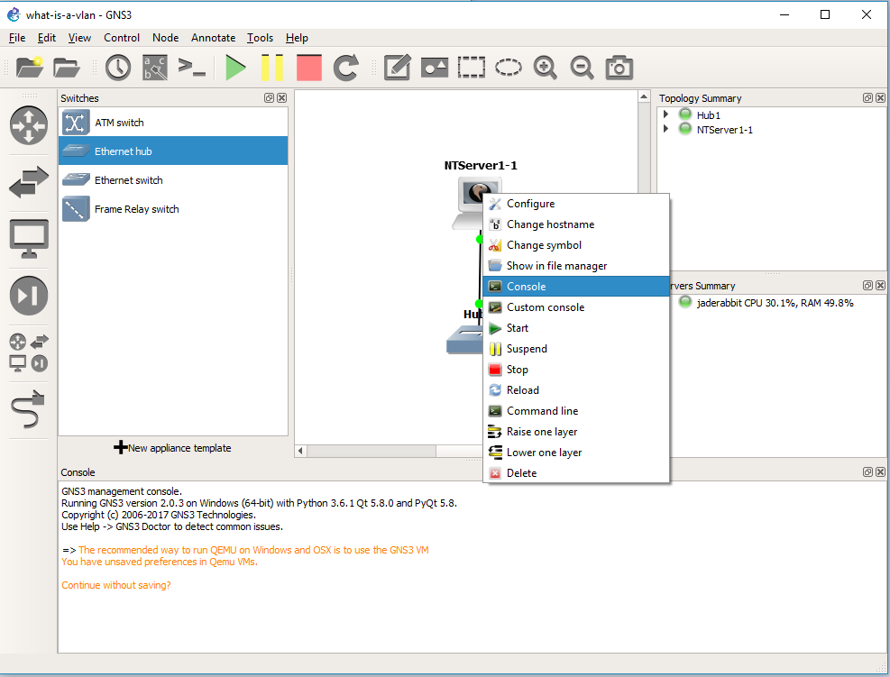
We then should right click on the link, and tell it to stop capturing.

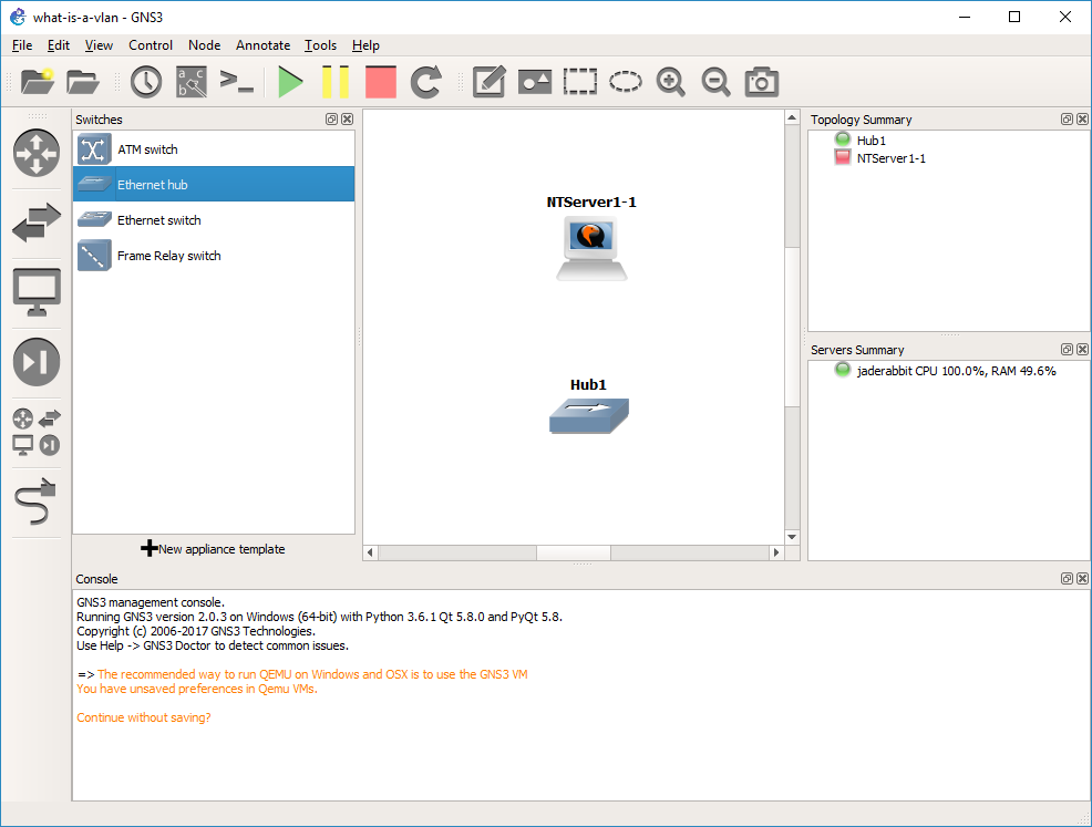
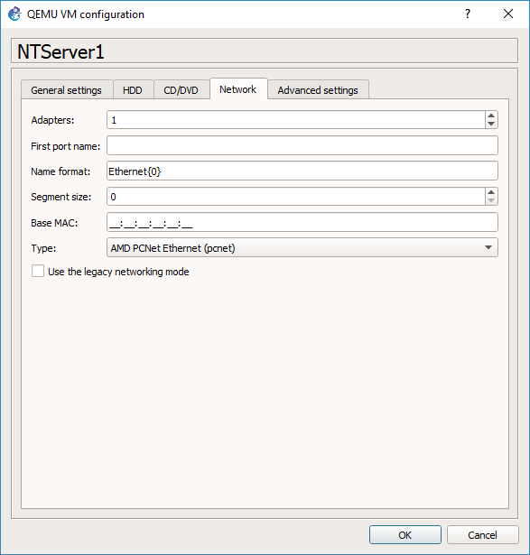
OK, now what about VLANs?  Let’s start with a simple lab.  We are going to get rid of the Hub for now, and add in two switches.  One switch will be our ‘core’ switch, the other will be our access switch.  We will then put our PC onto the access switch, and then setup an 802.1q trunk between the two switches, and then observer the NT broadcase traffic in the trunk so we can see the VLAN tag in action.

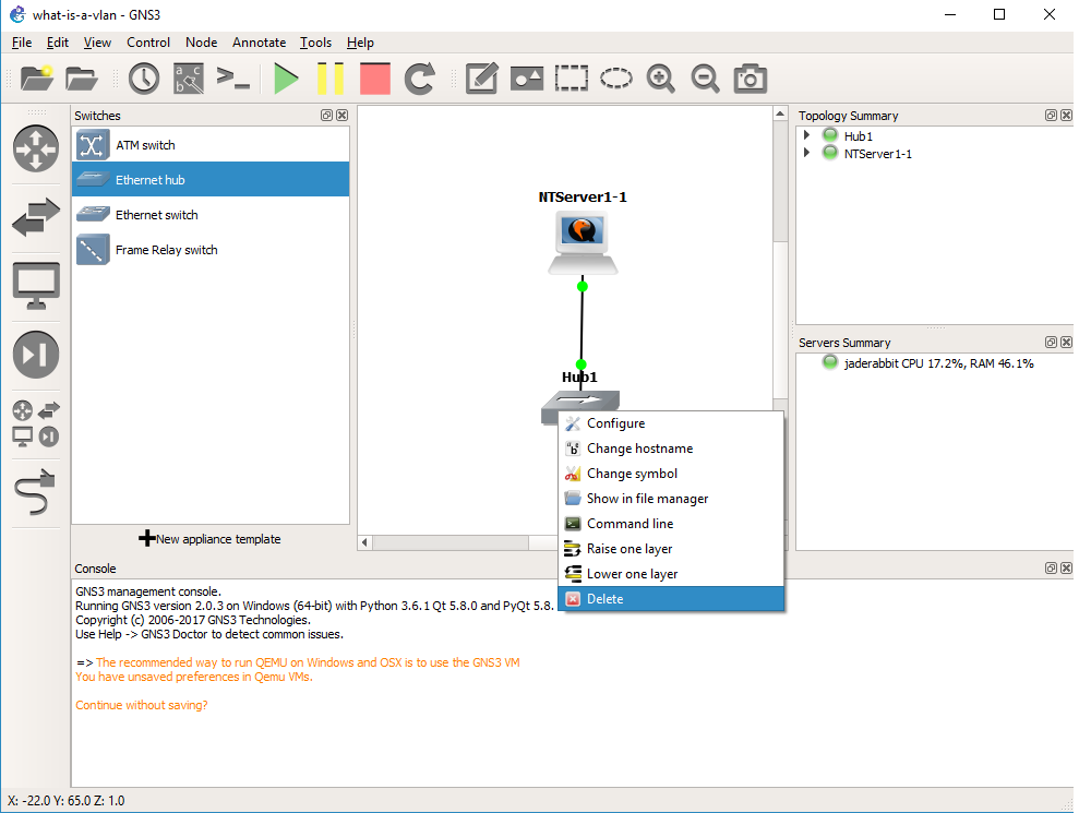
Right click on the hub, and delete it.

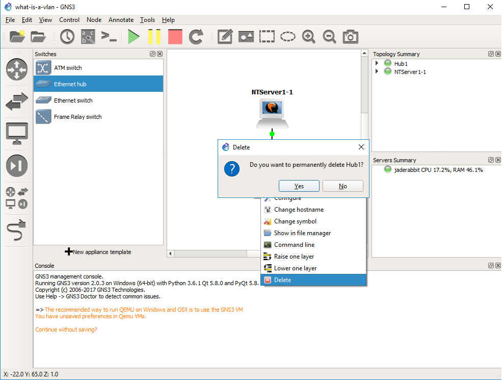
Yes we do want to delete it

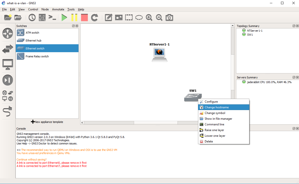
Drag out a switch, and then right click and rename it to core.

Now we are going to configure the core switch.

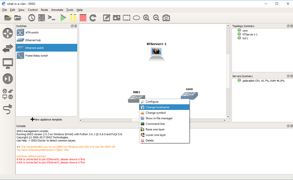
Right click on the core switch, and choose configure.

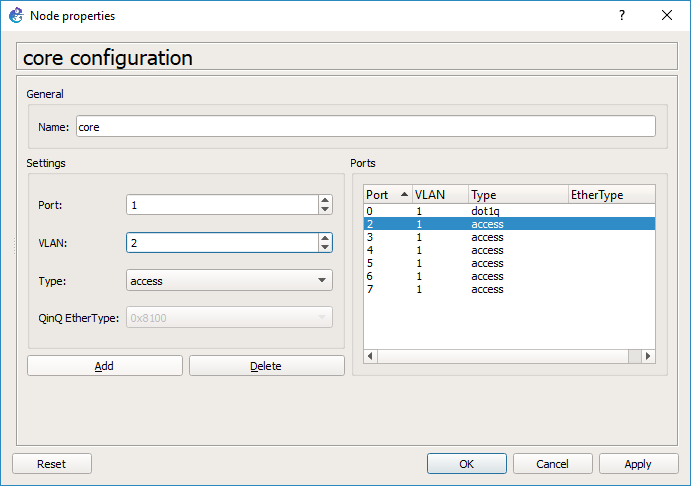
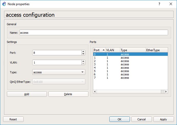
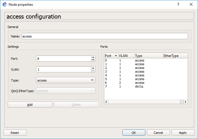
By default every port is on VLAN 1, and is a port type of ‘access’.  You would typically connect end devices like servers to access ports.  I probably should have deleted them all, but since we are going from my session I deleted ports 0 & 1.

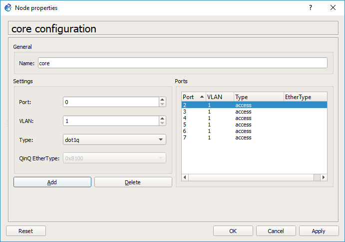
Now I’m going to add port 0 with a native VLAN of 1, but a type of dot1q. This port will be used to connect to the access switch.

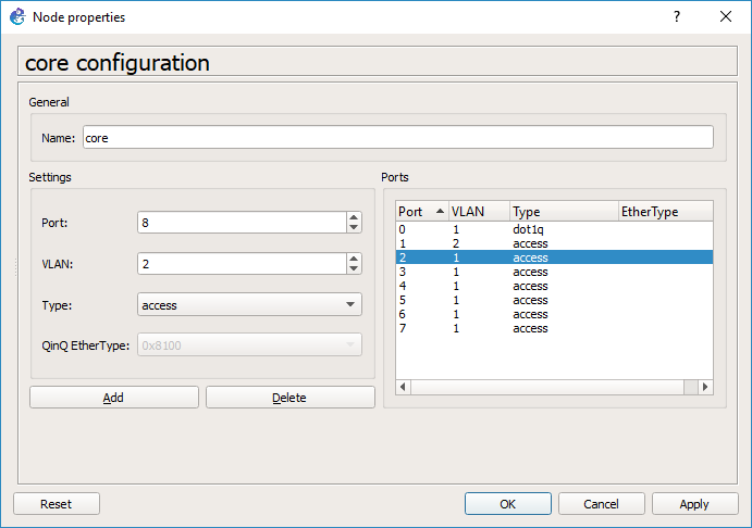
And then port 1 will be an access port on VLAN 2.  Hit OK and it’ll close the window.

And we are good to go.

*HOWEVER* this is a source of some confusion at least for me.  Go back and right click on the core switch, and look at the ports.  GNS3 for me changed the port numbers so it did not preserve my port choices, however there is still an access port on VLAN 2, and an 802.1q port.

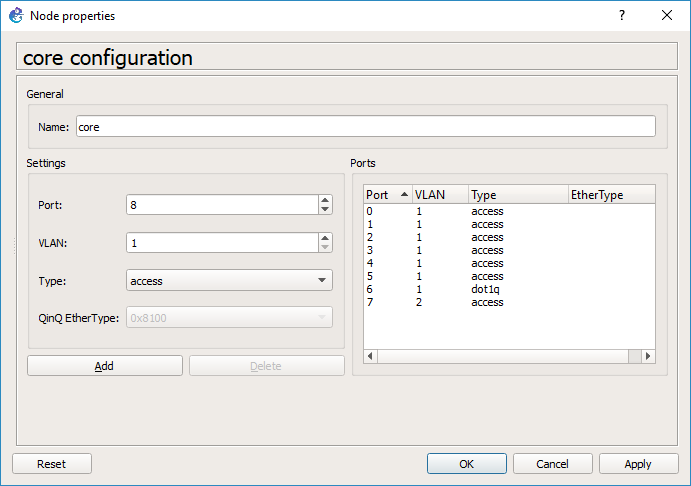
As you can see on the core switch, port 6 is now the dot1q trunk port, and port 7 is the VLAN 2 access port.

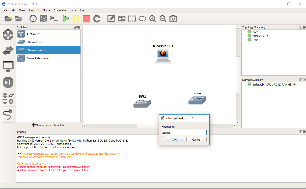
Add in a second switch, and change it’s hostname to access

Now let’s configure this switch the same way we configured the core.

Same steps, in that we delete some ports first

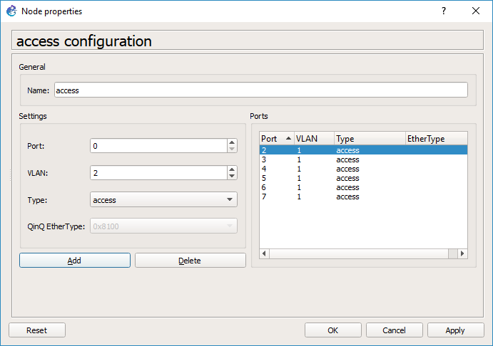
Add in an access port for the Qemu PC on VLAN 2

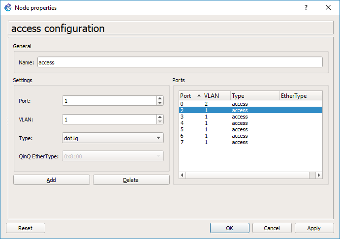
And then add in a port with a type of dot1q, and a native VLAN of VLAN 1.

And our access switch is configured, so you can hit OK.

As you can see GNS3 has changed our trunk port to port 7, and our Qemu access port is now port 6.  This should be a bug…

So with this confusion in mind we connect port 7 of the access switch to port 6 of the core switch, by selecting the cable tool, and the appropriate ports.

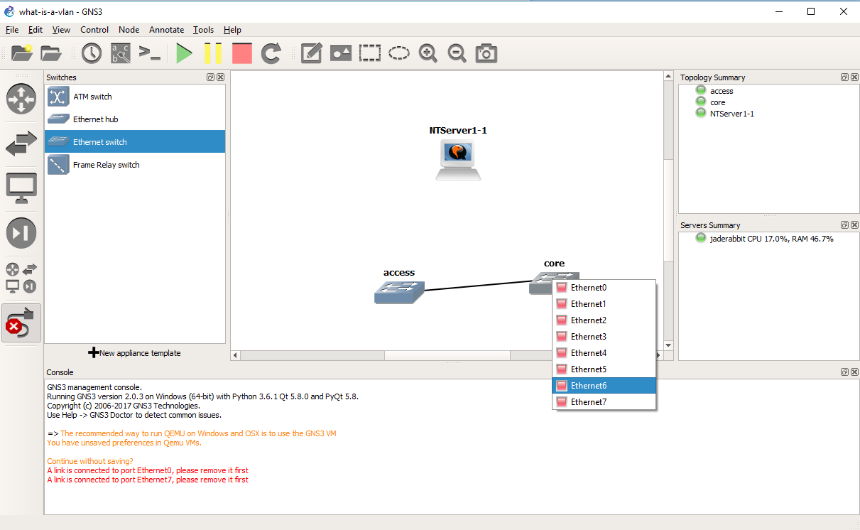
And we will now have connected the two switches.  Now to connect the Qemu PC.

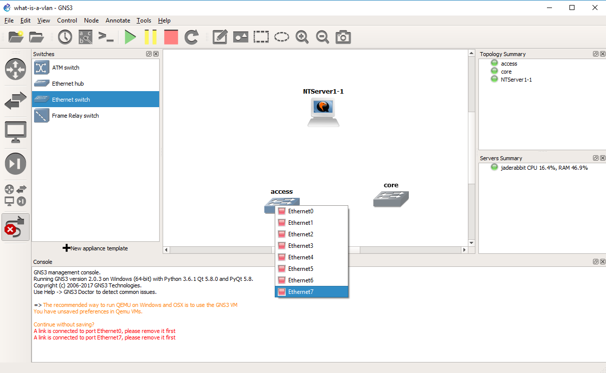
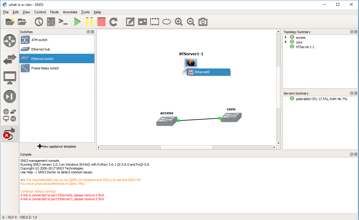
Again using the cable tool, it’s the only port on the Qemu VM

And to port 6 of the access switch.

Now we can start a capture on the connection between the two switches.  Right click on the link and start the capture.  It’ll be the same as last time, the default options are fine, and it’ll start Wireshark.

Now when the NT server sends a packet on the network, the access port is in VLAN 2.  Broadcast packets will be sent to all the other member ports on the network, in this case we do have an access port on the core switch in VLAN 2.  But while the packet is going between switches it needs a way to identify what VLAN the traffic came from, so as you can see from the capture There is now another protocol layer going on.  In this case we have an Ethernet II packet, but now the next layer is the 802.1Q frame, that gives the priority level, along with the VLAN number.  Then the NetBIOS packet is under that.  As you can see it is *NOT* TCP/IP only, but rather any Ethernet frame can be encapsulated in a VLAN, and then across 802.1q links they can be transmitted by encapsulating the packet in an 802.1q header to keep track of which VLAN the traffic was bound to.

But how about data egressing on the other side?

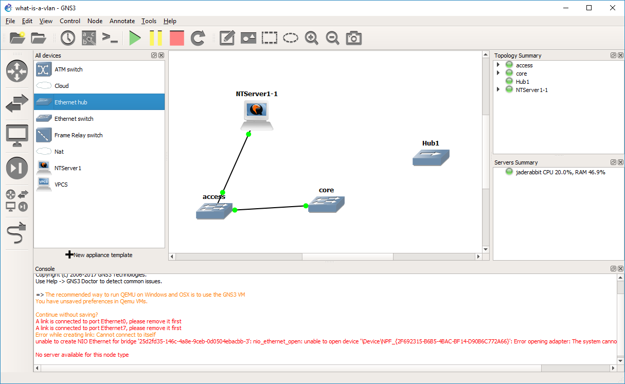
Let’s take a HUB and drag it out to the infrastructure pane.

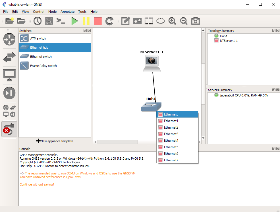
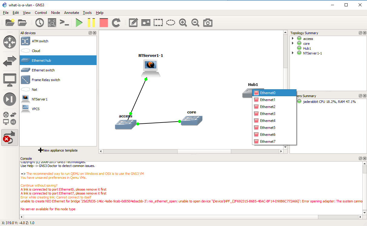
Now we are going to connect that hub on any port to the core switch.

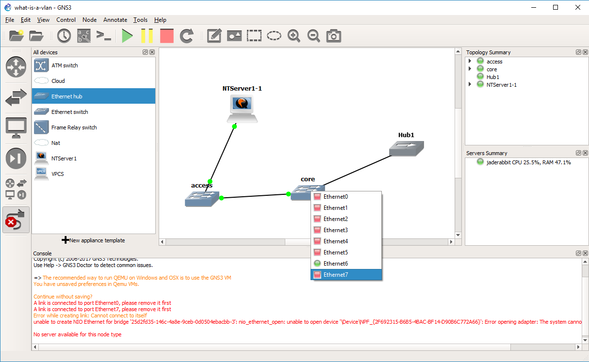
In this case, port 7 was our access port on VLAN 2.

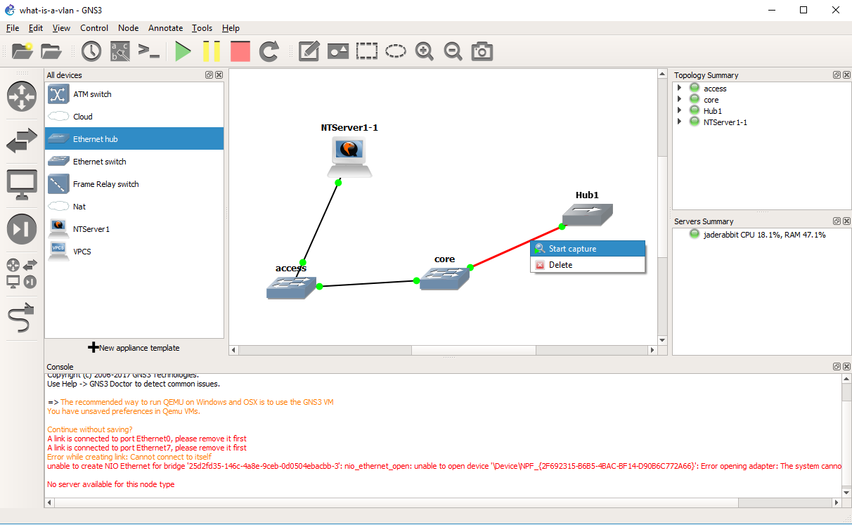
And now we can start a capture on the connection from the core switch to the hub.

And as you can see the NetBIOS arrives on the other side without any 802.1q header, and any machine on the other side wouldn’t even know it’s been through an 802.1q trunk, or that it’s even on a VLAN.

So why use VLANs?  Isn’t it easy enough to add infrastructure for every network as needed?  Sure you *could* but it becomes very costly.  And you end up supporting quite a number of devices.  Then it never fails that you have one user or device in part of the network that doesn’t warrent a good network connection, but when it breaks, like it always does they generate a lot of heat about it.  Just as LAN segmentation is a popular way corporations restrict internal access as they can have firewalls to control traffic entering and leaving each network.  But doing this the old way means that every tiny move add and change will require someone to do something physically making it very expensive to maintain.  VLANS solve these issues by letting you deploy good infrastructure everywhere that everyone can benefit from as they can share the hardware, however with things like QOS, you can ensure that they do not stomp on each-other for the uplinks, but they are isolated in their own VLANs.

And what is the big deal with 802.1q?  Well going back to our VLANs vs using physical switches, if we had 1,000 VLANS on a switch, and we wanted to connect 300 of those VLANs to a single server without 802.1q you would need 300 network cards.  Just as adding another switch would require you to use 1,000 ports to carry all those VLANs from one switch to another.  By using 802.1q to tag each VLAN through the trunk port it lets you use a single physical connection, and appear on each network.

Hopefully this is enough to get you started, both in terms of how to set things up, but what to look for.

What is a VLAN (part 5)

With the textmode setup complete, it’s time to do the graphical setup of Windows NT 4.0

Next

You can use any name/org

Select how many licenses you have for your NT Server.

Give the server a name

I’m not going to build a domain, so a stand alone server is fine.

You can give the Administrator account a password if you so desire.

I don’t need any emergency repair disk, as this server is the epitome of disposable.

I added all the components.  Again for this test it really doesn’t matter.

Configure the networking

Now for the fun part, we are going to configure the networking.

I’m sticking to ‘wired’ networking.  I’ll save RAS for another lifetime.

Everyone wants to be a webserver.  Sure why not.

You can either manually select a NIC, or just let it auto-detect.  We are going to auto-detect it though.

And it’ll correctly identify the AMD PCNet card.

I selected all the protocols available.  I didn’t bother adding other ones like AppleTalk.

Next..

Next

It’ll prompt for the media type and duplex.  The card isn’t real and it’ll work fine no matter what.  I just leave the options alone.

Our network doesn’t have any DHCP server.  Since we are plugged into a simple hub.  DHCP requests will fail.  Let’s give it a static address.  For Advanced people, yes you could wireshark on the wire to observe the DHCP.  We will touch on how to do that later, as I just want to get NT installed .

There is no need for a gateway.

We don’t have any bindings that need adjusting, so you can just hit Next

And Next again

Again, no domain, so run in workgroup mode.

Finish, although it’s far from over.

IIS components to install.  I just hit OK for the defaults.

Confirm the creation of the directory

And the child directories

And creating the IIS child directories

Gopher isn’t happy without a domain name, but I don’t care.

Select your timezone.  Or don’t.  This is from 1996, so many of the timezones are no-longer correct.  Just as DST has changed so many times.  But it really doesn’t matter yet again.

The display adapter is SVGA compatible.

Move the resolution slider to 800×600

Then hit OK.  It’ll want to test the resolution

Everything looks good

YES I saw the bitmap

OK

OK to accept the display at 800×600

Files will finally start to copy

And now we can finally restart are computer.

By default the NT Loader will wait for 30 seconds.  You can hit enter to get it to load right away or wait.

But we have now completed installing Windows NT, so we can now move on to capturing some traffic, aka part 6..

What is a VLAN (part 4)

In this post we are going to install Windows NT 4.0 Server into our VM.

The first step is to turn the VM on.  Simply right click on the VM, and choose Start. The red dot will then turn green.  Although it may appear that nothing is happening we just can’t see it yet.

Right click again, and choose the console, and VNC will then connect to the Qemu VM, and we can now interact with it.

And here is where we start installing Windows NT 4.0.  I’ll just put the keys in parenthesis of what I’m doing. In this case just hit:

(enter)

(enter)

(c)

(page down) until you get to the end, then hit (f8) to agree to the license

The default options are OK.  (enter)

(c)

(enter)

I chose NTFS for my server.  Although I’m not interested in creating a domain, so FAT will work too.  It really doesn’t matter.

(enter)

(enter)

(enter)

Waiting for the files to copy

(enter)

On reboot if you have selected NTFS it’ll convert the filesystem like this:

converting FAT to NTFS

After the conversion, NT will reboot again, then it’ll continue the setup process.

Otherwise you’ll just reboot directly into the graphical setup of Windows NT, and we can continue in part 5.

What is a VLAN (part 3)

In our previous post, we configured a Qemu template for Windows NT.

With the NT template ready we will be prompted to give this project a name.

So I called this one ‘what-is-a-vlan’ sticking with the theme.

Now we can drag components out.  I selected the NT template that I’ve created, and dragged it out to the design pane.  Now we have a computer!

I then selected a simple Ethernet hub, to begin verifying that our configuration is working.  Just drag it out to the toplogy pane.

Now for the fun part, we are going to connect the Windows NT VM to the Hub.  Right click on the Qemu VM, and it’s available Ethernet interfaces will pop up.  It only has one, so select Ethernet 0.

Now you can select the Hub to complete the connection.  Hubs repeat every packet they receive, and don’t change anything.  They offer zero intelligence, and have no way to save you from yourself, if you do anything stupid (see creating a loop).  Every packet that comes into a hub is sent to every port going out.  They don’t care about protocols, or anything they just simply repeat.


So this will be our simple network.  The next thing to do is to turn on our PC, and install Windows NT 4.0.  I’ll save that for the next step which you can follow here.  If you don’t care about installing Windows, then you can skip to the following step where we will do a simple packet capture of the NT machine connected to the hub so we can observe how it’s packets look.

What is a VLAN (part 2)

In the last post, we quickly went over the default install of GNS3.

We are now going to configure a QEMU template for Windows NT.  I’m going with Windows NT as its pretty resource low, has TCP/IP and other protocols like IPX/SPX which can be routed and NetBEUI which has to be bridged.

We are going to use the Qemu option

Although we do get this warning, it really doesn’t matter.  NT runs fine.

Give the machine a name

The default 256MB of RAM is more than enough.

Set the console to VNC, as NT is graphical

I set it to use the included qemu-2.4.0’s Qcow2 image format for the virtual hard disk

The default options are fine.

I’m not going to try to build anything that sophisticated, so 500MB is more than enough for NT 4.0 .  If you do want something more involved 2GB is the effective limit for a boot disk for NT 4.0 SP1

The default name is fine too.

We do however need to make some changes.  The network card needs to be the AMD PCnet version, and we need to add an additional flag to Qemu to restrict the CPU functionality to a 486 so that NT will install without any issues.

So the networking tab will let you change the type.  AMD PCNet is the one that is supported out of the box, and verified working!

On the Advanced settings tab, is where you can add the -cpu 486 flag, as indicated above.

On the CD/DVD tab, you will want to point it to an ISO of Windows NT.  It doesn’t matter if it’s Workstation, Server, Enterprise, Terminal Server.  They all install the same.

It will prompt you if you want to copy the ISO into the default images directory.  It really doesn’t matter one way or the other.

Qemu image configured for NT

Now the image is configured for NT.

Now we can continue to building our first topology (AKA Part 3).


What is a VLAN (part 1)

I got this question the other day, and I thought I’d make something of it.

“What is a VLAN?”

And more importantly…

Do you know of a good tutorial  / tool / game that I can use to understand vlans?

Sure do, GNS3.  So in this series as I know I’ll have to break it up as it’s going to be a LOT of images, I’m going to go over the installation of GNS3 on Windows (I’m not interested in obsolete package versions on whatever distro of the minute is the fancy in Linux world), I’ll go over how to use QEMU to install a Windows NT VM, go over how networking works with a simple hub, then install two switches, a trunk connection, and show how to observe the VLAN tagging in action.  Then add in other VM’s and more VLANs and then go over bridging vs routing.

The installation options are pretty simple.  I’m going to just stick with the default.

You can install it wherever you like.  You don’t have to install it on the C drive if you do not wish to.

And with that, hit next and it’s installed.

Im not interested in the solar winds stuff, so I just declined.  Nothing was missed.  After that go ahead and launch GNS 3, and you are welcomed with this screen.

I’m going to run everything on my computer.  I’m not going to get into slave machines, or even wondering why they don’t just launch multiple instances of dynamips where needed.  Or even what capabilities there are or even at the moment trying to force my MinGW Dynamips into the project.

It’ll pick a port and host binding.  It’ really doesn’t matter too much, maybe you want it for a proper LAN connection.  again I’m focused on using this as a self contained thing so the default option ought to work.

And with that said we can now move onto configuring a QEMU template for Windows NT (part 2).

Getting started with cisco VIRL L2 virtual Ethernet switches

Well for the longest time there was no generally available way to emulate a cisco L2 switch. right before Dynamips was abandoned, in 0.28RC1, there was actually some work on the the Catalyst 6000 Supervisor 1 line card, although no interfaces are supported, and it was largely seen as impossible at the time.

While there may have been leaks of the internal IOU or IOS on UNIX, these are even more dubious than buying your own cisco 7200 and running that IOS on Dynamips.  Indeed in the old days you’d no doubt find people with home labs that look something like this:

My sad lab.

So yeah, I know it’s not new but it was new to me.  But yes, VIRL is something us mere mortals can buy without a CCIE on hand, or a multi-million dollar contract on hand.  Although it isn’t free, but compared to everything else cisco sells it’s cheap…

So VIRL comes in a few different flavors.  They do have an ISO to run on bare metal x86 machines, OVAs for deployment on VMWare Workstation, and ESXi (Although for player you’ll have to get VIX and the vmnet config util from workstation, as I went through here & here).

Although that’s not so much what I’m interested in.  As always I’m more interested in something that lets me run it on my own.

Downloading the l2 image

So as of today, the latest file is vios_l2-adventerprisek9-m.vmdk.SSA.152-4.0.55.E, with the MD5 checksum of 1a3a21f5697cae64bb930895b986d71e.

So as a first test, you can run the L2 image with Qemu/KVM!  I found it works better renaming vios_l2-adventerprisek9-m.vmdk.SSA.152-4.0.55.E to vios_l2-adventerprisek9-m.vmdk.SSA.152-4.0.55.E.vmdk otherwise there was some issues with Qemu picking up the image.

The command line for a switch can be a little crazy so it’ll break some of it up onto separate lines.  This way you can see that I bound a few interfaces to listen on UDP, while most of them are unbound, but you get the idea.  Naturally it being a cisco product, it drives with a serial console.

qemu-system-i386w.exe
-m 768M
-smp cpus=1
-boot order=c
-drive file=vios_l2-adventerprisek9-m.vmdk.SSA.152-4.0.55.E.vmdk,if=ide,index=0,media=disk
-serial telnet:127.0.0.1:5000,server,nowait
-monitor tcp:127.0.0.1:51492,server,nowait
-net none -device e1000,mac=00:2e:3c:92:26:00
-device e1000,mac=00:2e:3c:92:26:01,netdev=gns3-1
-netdev socket,id=gns3-1,udp=127.0.0.1:10003,localaddr=127.0.0.1:10002
-device e1000,mac=00:2e:3c:92:26:02
-device e1000,mac=00:2e:3c:92:26:03
-device e1000,mac=00:2e:3c:92:26:04
-device e1000,mac=00:2e:3c:92:26:05,netdev=gns3-5
-netdev socket,id=gns3-5,udp=127.0.0.1:10000,localaddr=127.0.0.1:10001
-device e1000,mac=00:2e:3c:92:26:06 -device e1000,mac=00:2e:3c:92:26:07
-device e1000,mac=00:2e:3c:92:26:08 -device e1000,mac=00:2e:3c:92:26:09
-device e1000,mac=00:2e:3c:92:26:0a -device e1000,mac=00:2e:3c:92:26:0b
-nographic

In some ways, this is very much like running Solaris on QEMU via a serial console.  Once booted up, if you grab the console you’ll see:

l2’s grub console

Now, while I think it’s interesting to play with, but I know many people don’t like to setup and run a dozen programs manually, so how do we get this to run under GNS3!

As of right now the current version is 1.5.3, so let’s step through this real quick

Version 1.5.3

First when you fire it up (by default) you’ll get the option to specify using a local server

use local server

Next you will want to check the box to add a Qemu VM

Add a Qemu VM

give it a name like adventerprisek9-m.vmdk.SSA.152-4.0.55.E… Or anything else you wish to call it.

give it a name

Next I set the emulator to qemu-system-i386.exe and give it 768MB of RAM.

set the Qemu emulator & RAM

hit next, and then it’ll prompt to select a disk image.  In this example, remember I had renamed the downloaded VIRL image to have a VMDK extension.

select the image

Then GNS3 will prompt to add it to the default images directory

add it to the images directory

After that the wizard is complete.

Then finish

However there is still a bunch of settings that still need to change.  If you don’t make these changes you’ll have a switch with a single Ethernet port, and you will only be able to deploy a single switch, so that won’t be any fun!.

Once the wizard has finished you’ll be in the Preferences.  Just hit edit, on the template we just added, or otherwise it’s under Edit->Preferences.

Hit edit

First thing is kind of cosmetic, but go ahead and set the Category to Switches, so that way it ‘flows’ nice in the UI.

set category

Next hit the Network tab, and then add some adapters.

set the adapters to something more usable like 12

I’ve set the switch to 12 adapters.  The default of 1 isn’t too useful.  Next up hit the Advanced settings tab.  Be sure to un-check the ‘Use as a linked base VM’ . This will let you deploy multiple copies.  On Windows there is some weird issue where changes are seemingly not saved, so be sure to have a config backup strategy beyond saving the config locally.

uncheck the Use as linked base VM

Great, hit OK, and now we’ve got our L2 template for GNS3!

As a bonus, I put it on Linux, and it’ll run under KVM, however if you use the cisco downloaded files, you’ll see this error while booting:

-Traceback= 1DBB7C8z 8DBFE5z 90522Ez 904F50z 904D5Dz 900F45z 901B7Bz 901B0Fz 8D7C0Dz 8D7B0Dz 887061z 8BAE73z 8B9FD7z 8B7827z 8BCCC4z 8C0587z – Process “Async write process”, CPU hog, PC 0x008D7D62

Over and over, and it’ll be generally slow.  For some reason KVM/Qemu on Linux is struggling with the VMDK.  So the solution is to simply convert it from a VMWare VMDK into a Qcow2 image with:

qemu-img convert -f vmdk -O qcow2 vios_l2-adventerprisek9-m.vmdk.SSA.152-4.0.55.E.vmdk  vios_l2-adventerprisek9-m.vmdk.SSA.152-4.0.55.E.qcow2

Now using the qcow2 file, the switch will boot up just fine!

For any reference I’m running Ubuntu 16.10

and the KVM version is:

# kvm –version

QEMU emulator version 2.6.1 (Debian 1:2.6.1+dfsg-0ubuntu5.3), Copyright (c) 2003-2008 Fabrice Bellard

Getting dot1q to work between VMware and GNS3

So I had this fun episode where I was using Qemu to emulate an ASA, and it worked OK but it was incredibly slow, and I couldn’t put in multiple gigabytes of RAM.  So I thought I’d just dump Qemu and load it up on VMWare.

Well simple ethernet connections work just fine, but the dot1q interface (as this setup has about 50 different connections) doesn’t work at all.

The closest thing I could find was this interesting post, which states:

As I have attached previously there are 802.1q packets leaving the GNS emulated 7200 router but they are not being interpreted by the HOST-ONLY Adapter that is installed with workstation 11 nor does the HOST-ONLY adapter then TAG the l2 frames with the 802.1q ID.

So the host only adapters that I’m creating to give VMWare interfaces that GNS3 can latch onto, strip dot1q!

Well this is no good!

So I thought I’d try the older standby solution, which is the MS Loopback adapter, and try it that way.

Adding the adapter wasn’t too hard in 10, but they renamed it to the KM-TEST Loopback Adapter for some reason.  Anyways with the adapter installed, I removed all the bindings other than the VMware Bridge Protocol.

bindings for the loopback

bindings for the loopback

With that done, the next thing to do was run vmnetcfg, and bind the tunnel interface to a VMnet interface but not in the Host-only connection but bridged directly to the loopback adapter.

vmnetcfg

vmnetcfg

Now with the VMware part configured, it’s a matter of configuring a Cloud object in GNS3, and binding it to the loopback adapter, which in my case has the great name of ‘Ethernet 2’.

vmnetcfg

GNS3 bindings

From there I just attach the cloud to a dot1q ‘trunk’ interface on a GNS3 virtual ethernet switch.

With this proverbial house of cards built up, I can fire-up another VMware machine, in this case a Windows 2000 computer that is bound to a ‘normal’ VMnet adapter, with no fancy dot1a and..

It works!

It works!

I can get IE6 and all it’s glory on the internet.