WIth Windows NT installed, it’s time to look at it on the network side.
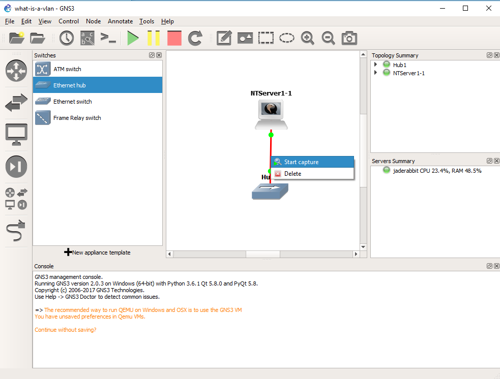 The killer feature of GNS3 is that we can inspect traffic everywhere we draw a connection. So simply right click on the connection from the Qemu VM to the Hub, and you can start a packet capture.
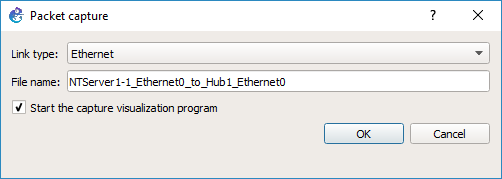 GNS3 will then prompt what the link type media is, in this case it’s Ethernet, and what the link name is. After hitting OK, it’ll then start WireShark on the virtual link.
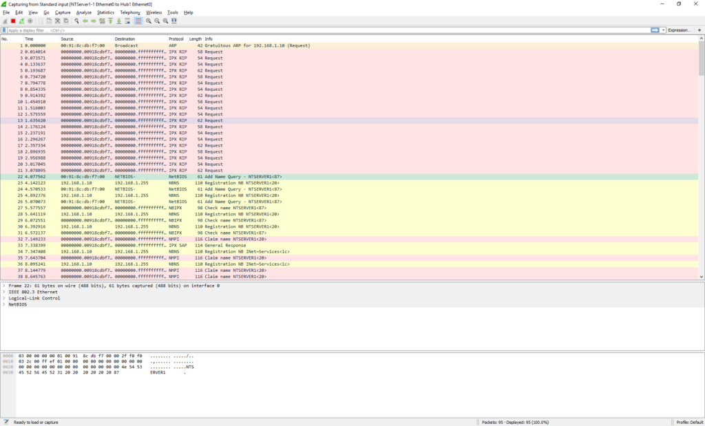 And in no time we can see the NT machine broadcasting on the network. OK everything is looking fine.
As you can see our packet is an 802.3 Ethernet packet, with a LLC header, and a NetBIOS packet. This is what we are expecting as the connection to the hub is ‘raw’.
Now that we have verified that we can connect to the network and capture, we can close Wireshark.
 We then should right click on the link, and tell it to stop capturing.
OK, now what about VLANs? Let’s start with a simple lab. We are going to get rid of the Hub for now, and add in two switches. One switch will be our ‘core’ switch, the other will be our access switch. We will then put our PC onto the access switch, and then setup an 802.1q trunk between the two switches, and then observer the NT broadcase traffic in the trunk so we can see the VLAN tag in action.
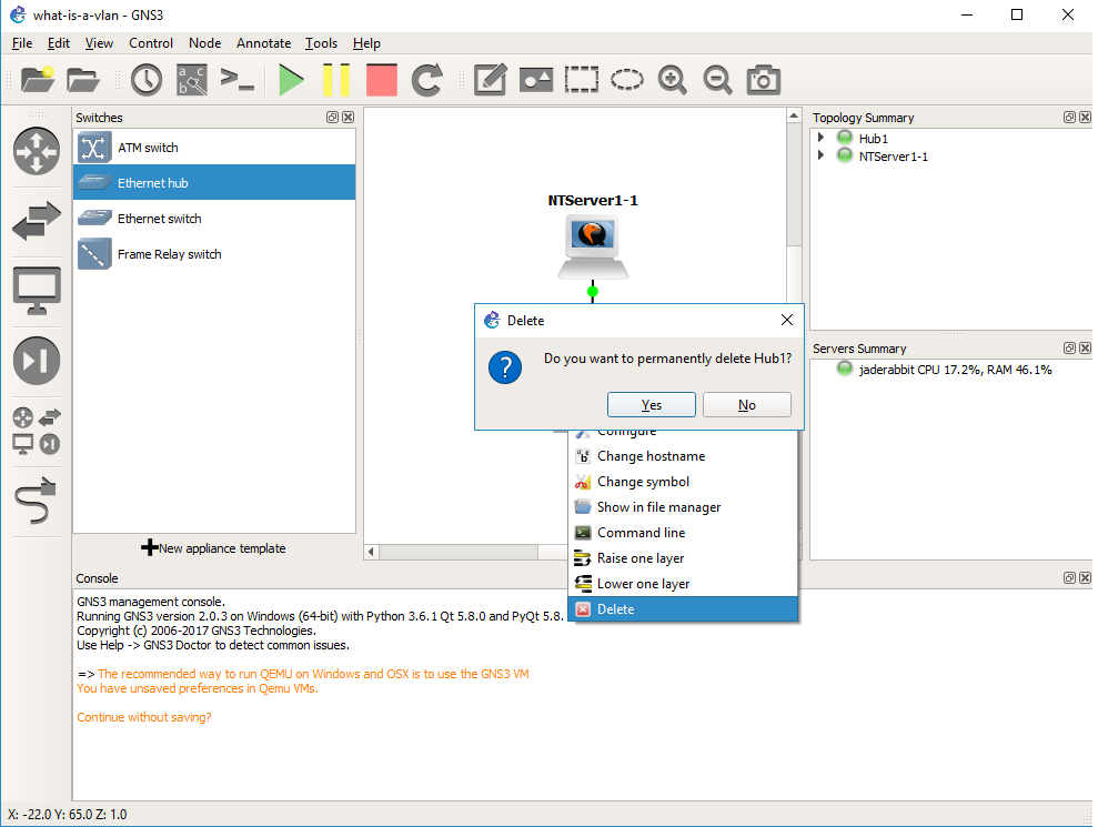
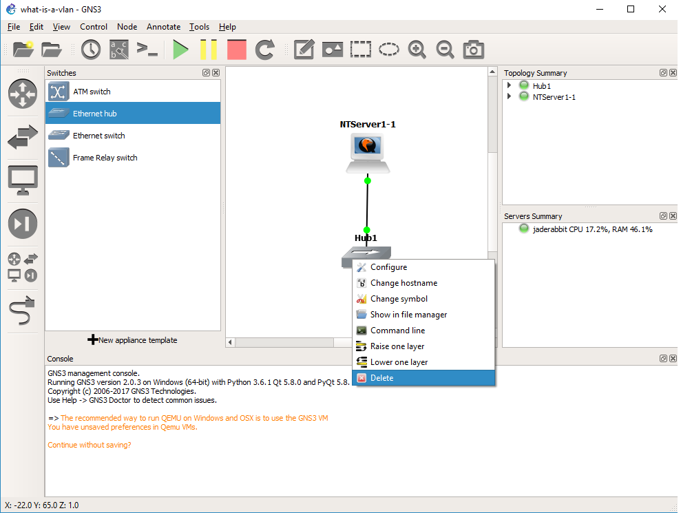 Right click on the hub, and delete it.
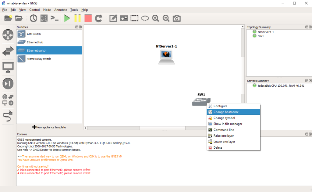 Drag out a switch, and then right click and rename it to core.
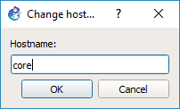 Now we are going to configure the core switch.
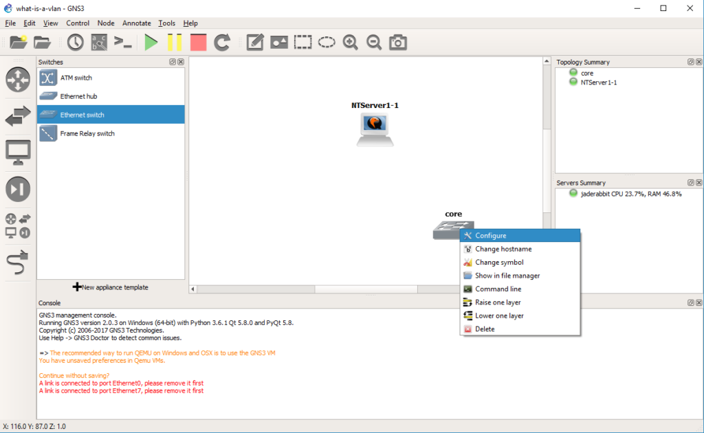 Right click on the core switch, and choose configure.
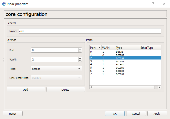
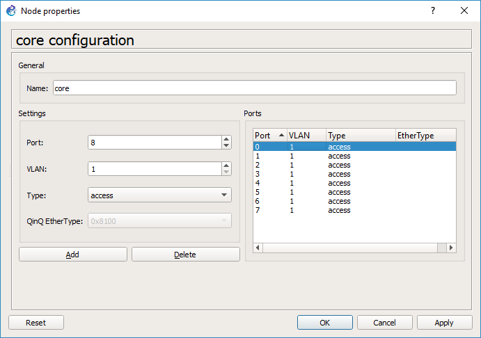 By default every port is on VLAN 1, and is a port type of ‘access’. You would typically connect end devices like servers to access ports. I probably should have deleted them all, but since we are going from my session I deleted ports 0 & 1.
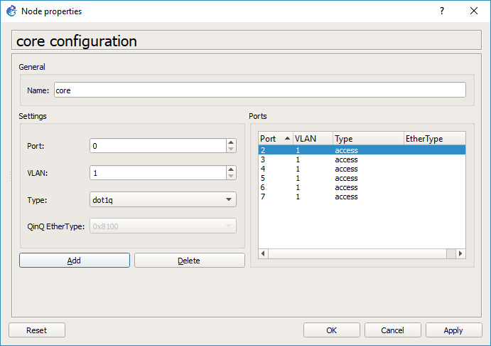 Now I’m going to add port 0 with a native VLAN of 1, but a type of dot1q. This port will be used to connect to the access switch.
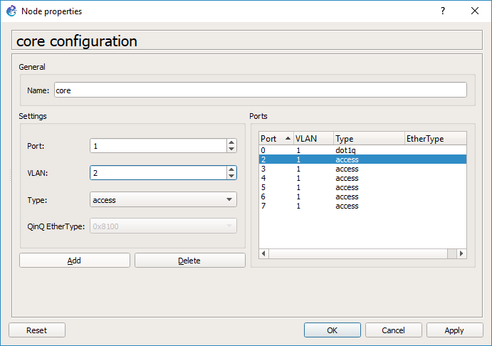 And then port 1 will be an access port on VLAN 2. Hit OK and it’ll close the window.
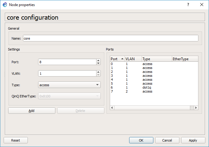
*HOWEVER* this is a source of some confusion at least for me. Go back and right click on the core switch, and look at the ports. GNS3 for me changed the port numbers so it did not preserve my port choices, however there is still an access port on VLAN 2, and an 802.1q port.
As you can see on the core switch, port 6 is now the dot1q trunk port, and port 7 is the VLAN 2 access port.
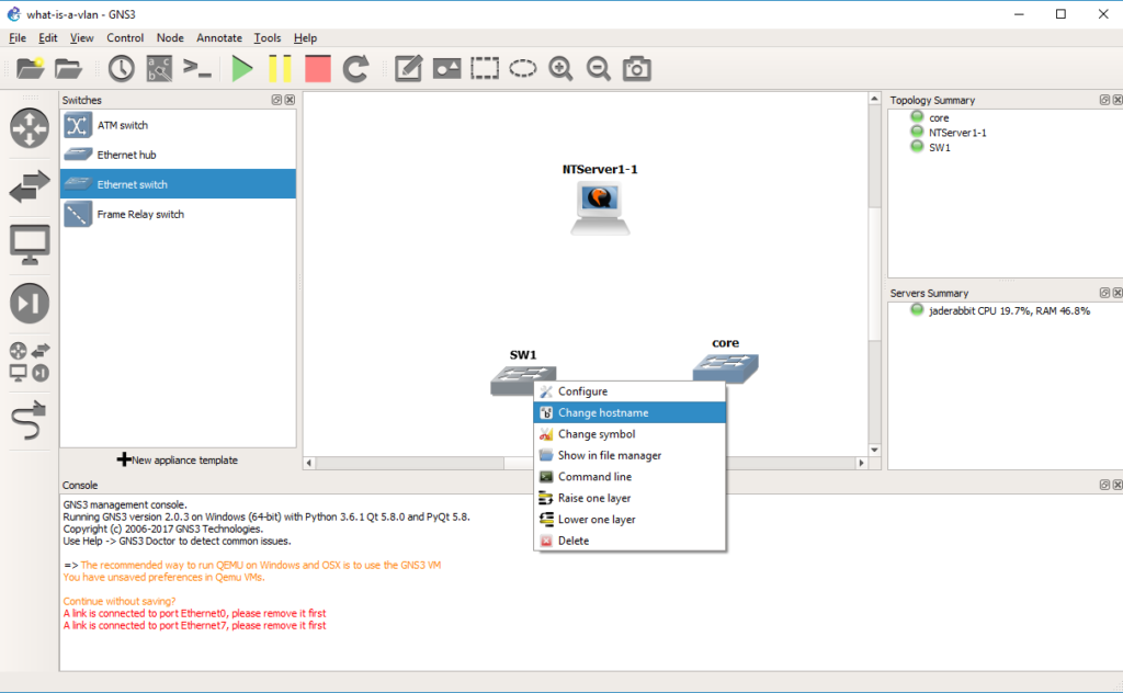 Add in a second switch, and change it’s hostname to access
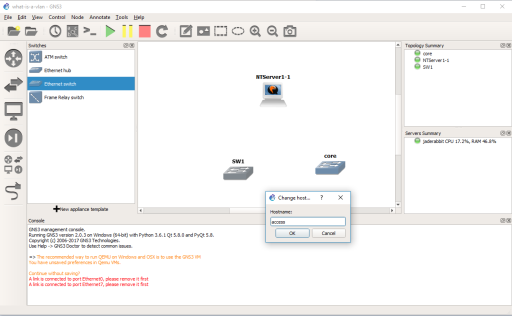 Now let’s configure this switch the same way we configured the core.
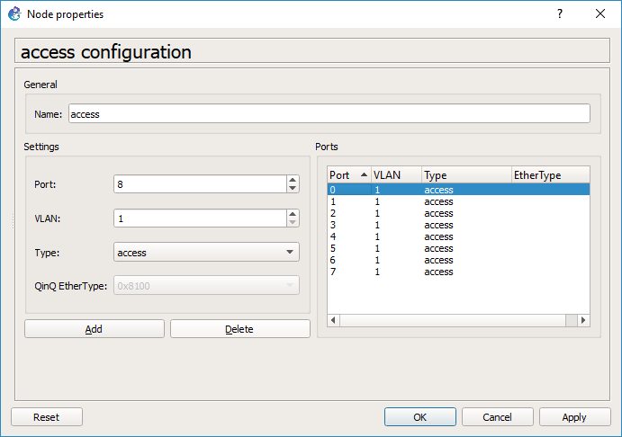 Same steps, in that we delete some ports first
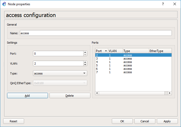 Add in an access port for the Qemu PC on VLAN 2
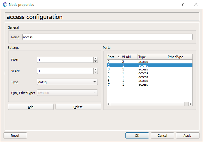 And then add in a port with a type of dot1q, and a native VLAN of VLAN 1.
 And our access switch is configured, so you can hit OK.
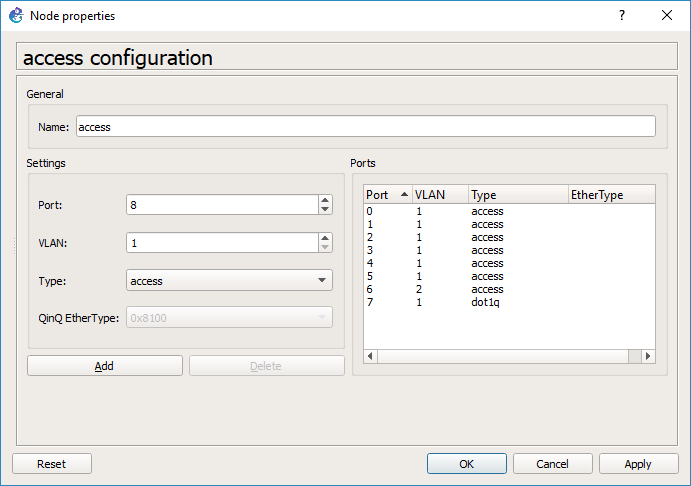 As you can see GNS3 has changed our trunk port to port 7, and our Qemu access port is now port 6. This should be a bug…
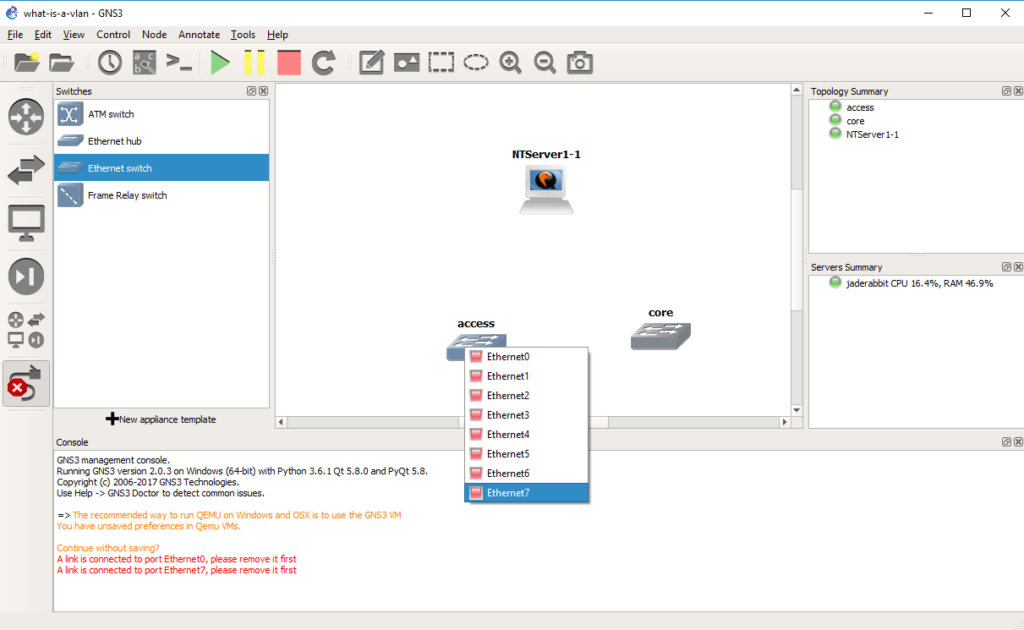 So with this confusion in mind we connect port 7 of the access switch to port 6 of the core switch, by selecting the cable tool, and the appropriate ports.
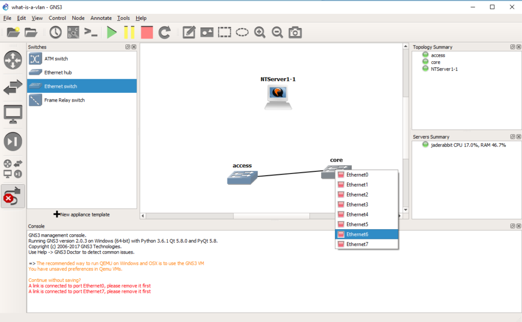 And we will now have connected the two switches. Now to connect the Qemu PC.
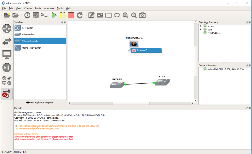 Again using the cable tool, it’s the only port on the Qemu VM
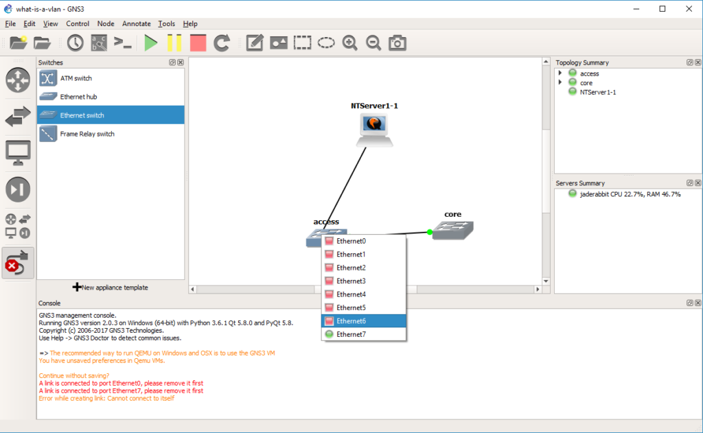 And to port 6 of the access switch.
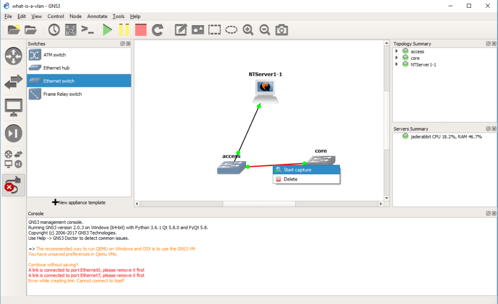 Now we can start a capture on the connection between the two switches. Right click on the link and start the capture. It’ll be the same as last time, the default options are fine, and it’ll start Wireshark.
Now when the NT server sends a packet on the network, the access port is in VLAN 2. Broadcast packets will be sent to all the other member ports on the network, in this case we do have an access port on the core switch in VLAN 2. But while the packet is going between switches it needs a way to identify what VLAN the traffic came from, so as you can see from the capture There is now another protocol layer going on. In this case we have an Ethernet II packet, but now the next layer is the 802.1Q frame, that gives the priority level, along with the VLAN number. Then the NetBIOS packet is under that. As you can see it is *NOT* TCP/IP only, but rather any Ethernet frame can be encapsulated in a VLAN, and then across 802.1q links they can be transmitted by encapsulating the packet in an 802.1q header to keep track of which VLAN the traffic was bound to.
But how about data egressing on the other side?
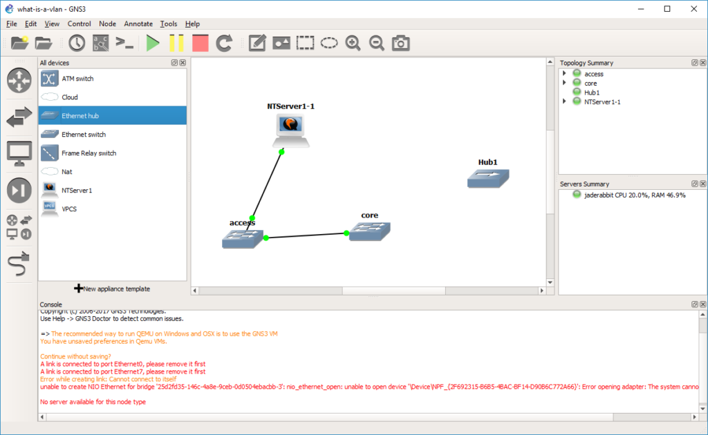 Let’s take a HUB and drag it out to the infrastructure pane.
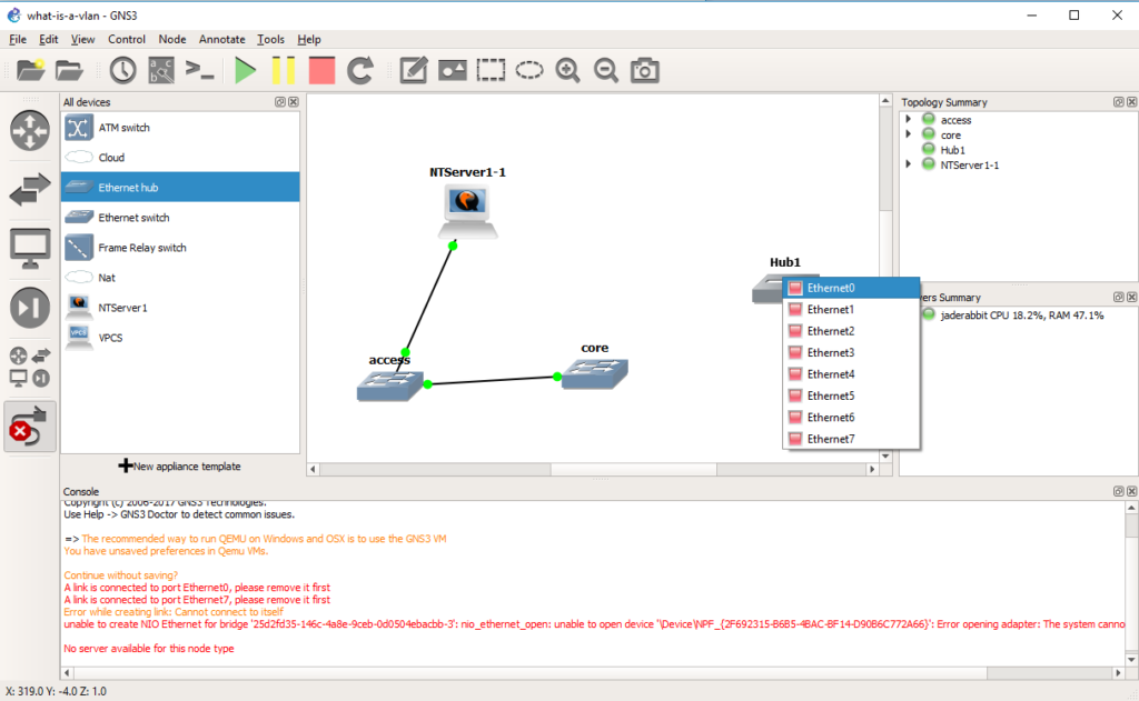 Now we are going to connect that hub on any port to the core switch.
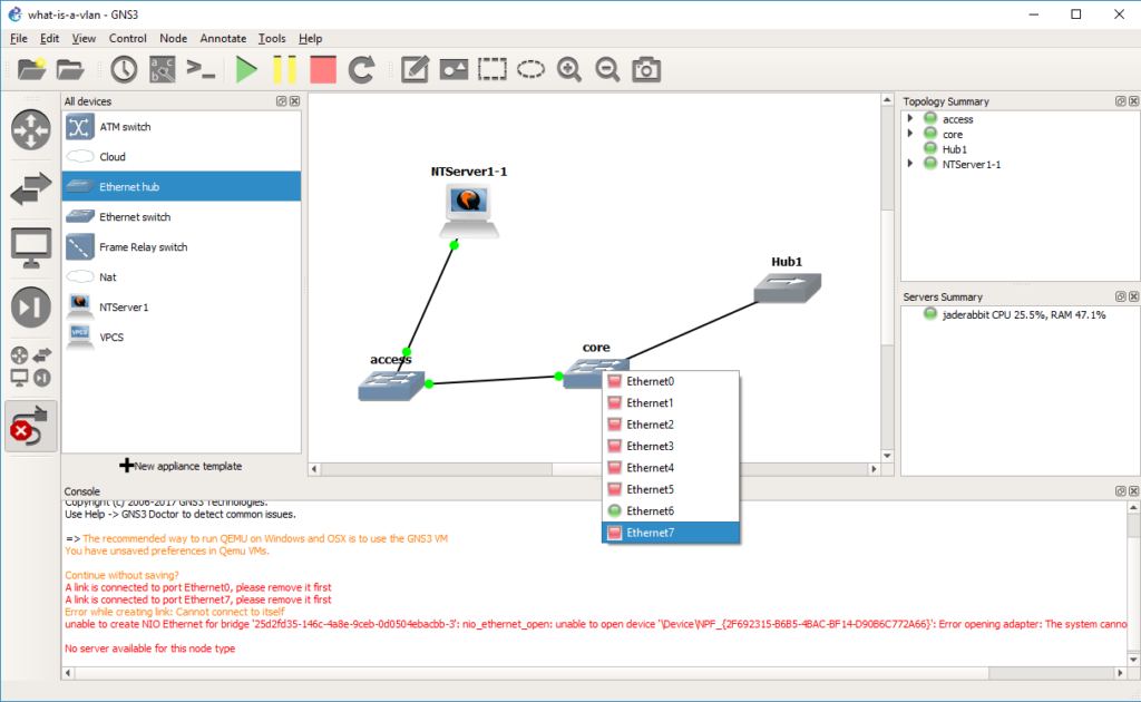 In this case, port 7 was our access port on VLAN 2.
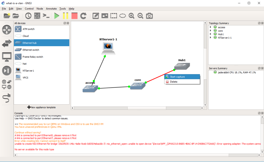 And now we can start a capture on the connection from the core switch to the hub.
 And as you can see the NetBIOS arrives on the other side without any 802.1q header, and any machine on the other side wouldn’t even know it’s been through an 802.1q trunk, or that it’s even on a VLAN.
So why use VLANs? Isn’t it easy enough to add infrastructure for every network as needed? Sure you *could* but it becomes very costly. And you end up supporting quite a number of devices. Then it never fails that you have one user or device in part of the network that doesn’t warrent a good network connection, but when it breaks, like it always does they generate a lot of heat about it. Just as LAN segmentation is a popular way corporations restrict internal access as they can have firewalls to control traffic entering and leaving each network. But doing this the old way means that every tiny move add and change will require someone to do something physically making it very expensive to maintain. VLANS solve these issues by letting you deploy good infrastructure everywhere that everyone can benefit from as they can share the hardware, however with things like QOS, you can ensure that they do not stomp on each-other for the uplinks, but they are isolated in their own VLANs.
And what is the big deal with 802.1q? Well going back to our VLANs vs using physical switches, if we had 1,000 VLANS on a switch, and we wanted to connect 300 of those VLANs to a single server without 802.1q you would need 300 network cards. Just as adding another switch would require you to use 1,000 ports to carry all those VLANs from one switch to another. By using 802.1q to tag each VLAN through the trunk port it lets you use a single physical connection, and appear on each network.
Hopefully this is enough to get you started, both in terms of how to set things up, but what to look for.


So much effort about a “tag” for VLAN number, which is important for network switching, but less important for single machines ?
Sometimes you want a machine to appear on more than one VLAN. I need to finish this up, but when you have servers like VMWare etc they tend to want to be on more than one network at a time. It may be a lot of work for the house, and frankly really unneeded but it’s more so for companies, and or people who want to have untrusted and separated networks.
can you expand this guide and setup some routing with a cisco router adding some netware servers and Windows NT one (what is the deal with gopher not working without a domain name: https://i0.wp.com/virtuallyfun.com/wordpress/wp-content/uploads/2017/10/gns3-2.0.3-install-NT-4.0-41.png?w=642&ssl=1 (how can you fix that error?) and build a network in GNSS3
I was thinking of adding stuff like that, although I wasn’t sure anyone actually read all that 6 parter as it was… well pretty step by step.
As for the images thing, I clicked some ‘wordpress CDN’ network thing. I thought I’d give it a try as I tend to use a LOT of images, and thought it may speed things up for users. Gopher is fun from time to time, but my Windows server was destroyed as it was just a cheap instance…