
On sale now!
That’s right for you fans of the cisco hold music, you can now buy the single on iTunes!

On sale now!
That’s right for you fans of the cisco hold music, you can now buy the single on iTunes!
choices..
Well considering what a hit it was, the last time I did this, I thought I’d give it another go!
And after a bit of fighting, I got it to run!
Now what were the obstacles? Â Well for starters not having a full libc certainly hurts things. Â Things like a malloc. Â And without getting fancy with the memory map I did the lamest cheat ever, which is a 1MB static array I just handed out with a fake malloc (no free, I didn’t bother to track chunks), and you know it works enough.
Also I need to read files, and I need to look more into the hardware to see how to do that. Â There seems to be plenty of hooks for NVRAM, but the ROMMON substitute doesn’t seem to support them. Â Also there is no ROMMON hook for reading from the console! Â The MIPS cilo is more ROMMON dependent, while the PowerPC c1700 talks to the uart directly so this is a PowerPC thing for right now.
I also learned something exciting about ld, which is how it can absorb binary images into objects, that you can link and access directly into your program! Â No more having to convert it to hex, make these insane headders that CPP may or may not bomb over. Â No you can make them objects right away!
In this example I read the file planetfa.dat as BINARY, and encapsulate it in an object file called planetfa.o . It’ll now have a symbol name of _binary_planetfa_dat_start for where the image begins, _binary_planetfa_dat_size will tell me how big it is in memory, and _binary_planetfa_dat_end will mark the end of this ‘file’ in memory.
Now in the old days when it was a file I could access it like this:
fread ((char *)ptr,block_size,(int)num_blocks,game_file);
But that won’t work. Â So now instead of calling fopen/fclose (which don’t exist in CILO), I set a counter to what my current offset is, change the ‘fseek’ to just set the global counter to where it should be, and when I fread I just memcpy:
I suppose I could just have wrapped the f* calls into some emulation library but I don’t need to get all that crazy sophisticated.
Local UUID: 0450c178-6480-11e5-a559-019031cf957a
Pcap version [WinPcap version 4.1.3 (packet.dll version 4.1.0.2980), based on libpcap version 1.0 branch 1_0_rel0b (20091008)]
Unsure if this file (c1700_i0_rommon_vars) needs to be in binary mode
Virtual RAM size set to 4 MB.
IOS image file: ciscoload.bin
ILT: loaded table “mips64j” from cache.
ILT: loaded table “mips64e” from cache.
ILT: loaded table “ppc32j” from cache.
ILT: loaded table “ppc32e” from cache.
vtty_term_init
CPU0: carved JIT exec zone of 64 Mb into 2048 pages of 32 Kb.
C1700 instance ‘default’ (id 0):
VM Status : 0
RAM size : 4 Mb
NVRAM size : 32 Kb
IOS image : ciscoload.bin
Loading BAT registers
Loading ELF file ‘ciscoload.bin’…
ELF entry point: 0x8000d9c8
C1700 ‘default’: starting simulation (CPU0 IA=0xfff00100), JIT enabled.
ROMMON emulation microcode.
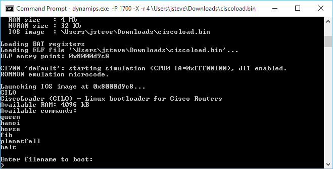
Launching IOS image at 0x8000d9c8…
CILO
CiscoLoader (CILO) – Linux bootloader for Cisco Routers
Available RAM: 4096 kB
Available commands:
queen
hanoi
horse
fib
planetfall
halt
Enter filename to boot:
malloc 64512 offset is 0 offset is now 64522
malloc 38912 offset is 64522 offset is now 103444
PLANETFALL
Infocom interactive fiction – a science fiction story
Copyright (c) 1983 by Infocom, Inc. All rights reserved.
PLANETFALL is a trademark of Infocom, Inc.
Release 37 / Serial number 851003
Another routine day of drudgery aboard the Stellar Patrol Ship Feinstein. This
morning’s assignment for a certain lowly Ensign Seventh Class: scrubbing the
filthy metal deck at the port end of Level Nine. With your Patrol-issue
self-contained multi-purpose all-weather scrub brush you shine the floor with a
diligence born of the knowledge that at any moment dreaded Ensign First Class
Blather, the bane of your shipboard existence, could appear.
Deck Nine
This is a featureless corridor similar to every other corridor on the ship. It
curves away to starboard, and a gangway leads up. To port is the entrance to
one of the ship’s primary escape pods. The pod bulkhead is closed.
Deck Nine Score: 0/4451
PLANETFALL
Infocom interactive fiction – a science fiction story
Copyright (c) 1983 by Infocom, Inc. All rights reserved.
PLANETFALL is a trademark of Infocom, Inc.
Release 37 / Serial number 851003
Deck Nine Score: 0/4451
>
For anyone crazy enough, you can find my MinGW Dynamips on sourceforge, cross compilers for PowerPC, and the branch of the firmware source that includes InfoTaskForce, and the binary image.
While I don’t want to write an OS for this, it is almost tempting. Â Or go the other route, and add in some non router based hardware… Like audio hardware, or a framebuffer.
Does anyone have a 1700 to test to see if any of this works? Â Or a 7200?! 😀
Continuing on from yesterdays adventure I built the PowerPC compiler to support the Cisco 1700 (and maybe the 7200 NPE-G2?).
Much to my surprise, this one works too!
Loading ELF file ‘../ciscoload.bin’…
ELF entry point: 0x8000cba0
C1700 ‘default’: starting simulation (CPU0 IA=0xfff00100), JIT enabled.
ROMMON emulation microcode.
Launching IOS image at 0x8000cba0…
CIL
Error: Unable to find any valid flash! Aborting load.
Awesome!
Building this was a lot more fun. I thought I could sidestep building a Linux to PowerPC ELF cross compiler, but as it turns out, to bootstrap libgcc, you really need a compiler that can do this. But with the steps basically down, it was trivial to whip up.
Although I did keep on hitting this error with the Win32 tools that “-mstrict-align” is not supported, while trying to build the startup and libgcc sources using the MinGW targeted compiler through wine. But once I had a native Linux to PowerPC toolchain in place, not only could I build the Windows based compiler, but I can also use the flag -mstrict-align on Windows without it complaining. So lesson learned, have a cross compiler built to the final target to make life easier when building a Canadian cross.
As always, building the binutils package was a snap, just run:
./configure --host=i686-mingw32 --target=ppc-elf -prefix=/ppc
and I had my assembler/linker/librarian in no time.
Because of the aforementioned -mstrict-align issue, I got more creative with the parameters for GCC.
./configure --target=ppc-elf --prefix=/ppc --disable-nls --disable-werror --disable-libssp --without-headers --disable-threads --build=i486-linux-gnu --host=i686-mingw32
But with the Linux to PowerPC cross compiler in place, I was able to quickly generate a working toolchain.
I copied in CILO, and added in a build batch file to manually build it, and updated the test directory to run it.
So for those who are interested here is my toolchains:
And a mirror on sourceforge of my cross toolchains, PowerPC and MIPS.
As a minor addendum, The 1700 can run stuff that is far more complicated than the MIPS. I’m not sure why I get so many TLB violations for doing something more complicated but I (poorly) ported aclock to run on the cisco 1700!
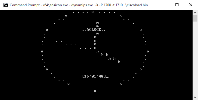
The Dynamips ROMMON emulator doesn’t provide the keyboard input function call so it can’t read from the keyboard. Also it can’t read the clock, so I have it running 250,000 dhrystones between clock ticks. Although I think that is far too many, maybe 125,000 would be more like it but it runs on the PowerPC. While on the MIPS I get nothing but this:
*** TLB (Load/Fetch) Exception ***
PC = 0x80008964, Cause = 0x00008008, Status Reg = 0x00408103
Oh well. Maybe it’s a stack problem I guess I’ll have to break down and do a memory map and write a malloc if I want to go down this road. Although back in 1999 this would be incredible but today I don’t think anyone would run anything but IOS on their cisco hardware.
I’ve tried to build a cross compiler on MinGW32 before, and despite there being obvious steps on how to do it, I’ve never gotten it to work. Now I’ve built cross compilers before so it’s not like I don’t have any clue on what I’m doing, but the problem is that Windows isn’t UNIX, and I don’t want to use Cygwin.
So that enters another fun possibility known as the Canadian Cross, which is using a machine in the middle to build a compiler. As we all know, Linux is great for building and running GNU software, so a Linux machine to build my cross compiler would be the best. Now the whole point of this is that I wanted to build a MIPS program to run on Dynamips. And through a LOT of googling, I managed to find this program called CILO the cisco Linux loader. Now as far as I can tell the people trying to port Linux the the MIPS based cisco routers (3600 and 7200) never succeed, but they did manage to leave this bootloader behind. And compiling it was very tricky as they gave no hints on what to use. So with a lot of trial and error I found that binutils 2.18 is the minimal version that will work as the code depends on being able to do register aliasing which isn’t present in previous versions. Also according to this, they were using gcc 4.1.2 in their Linux port. So with some luck I did mange to get CILO to build with a cross compiler on Linux. Which was pretty awesome to see Dynamips run a C program!
But that doesn’t help me on the Windows side.
Now the first thing that I’d normally do is install the default MinGW cross tools, but because I need ancient binutils and GCC support as newer versions not only won’t work for what I want, but won’t build older versions I tried to keep things in step. This meant on Linux I first had to build a Linux to Windows cross compiler using binutils version 2.25.1 and GCC version 4.1.2 . Configuring and building binutils was a snap with:
./configure --target=i686-mingw32 --prefix=/usr/local/mingw32
And configuring and building gcc was also a snap with:
./configure --target=i686-mingw32 --prefix=/usr/local/mingw32 --disable-libssp
I thought I could just use a new mingwrt and w32api but that proved disastrous as the newer libs gave me this fun error on trying to link a Win32 execuatable:
undefined reference to `___chkstk_ms’
And googling that around the consensus is that your binutils, and gcc is too old, and upgrade, granpa! But I want old software so I naturally have to just use older versions, and for gcc 4.1.2 I wanted:
Now I could build and link and test my Linux to Windows toolchain!
Now for the crazy part.
First I need a binutils, so I configured binutils 2.18 like this:
./configure --host=i686-mingw32 --target=mips-elf --prefix=/mips
And sure enough with a little prodding I had a MIPS assembler/linker/librarian and all that fun stuff!
Next was a little (ok a LOT) more fun which was building gcc.
After about 30 aborted attempts I finally got gcc to build with this:
./configure --target=mips-elf --prefix=/mips --disable-libssp --build=i486-linux-gnu --host=i686-mingw32
The fun part of course is that during the build, gcc will want to run the cross compiler and dump it’s host machine bit types by running ‘xgcc -dumpspecs’. Well thankfully via wine, Linux can run Win32 execuatables so I saved myself a few minutes by not having to copy over the partial compiler, and run the command, and transfer the results back.
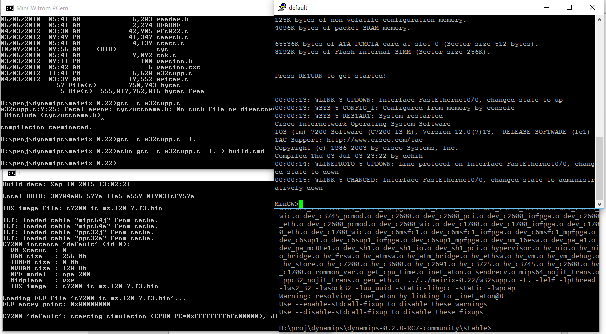
So with a bit more hand holding on the build I finally got it to finish compiling by linking /bin/true to fix-headers . What a mission. Now I excitedly transfered my build to my Windows host, and setup some environment variables and built the hello world cisco application, and, it worked! (well crashes the same way as the pre-built one, but it does say:
C7200 ‘default’: starting simulation (CPU0 PC=0xffffffffbfc00000), JIT disabled.
ROMMON emulation microcode.
Launching IOS image at 0x80008000…
Hello World!
Image returned to ROM.
Reset in progress…
Which is pretty cool!
I tried to merge in a make utility but that turned out to be kind of screwed up, so I just copied the cross steps from Linux, and now I can build cilo on Windows!
C7200 ‘default’: starting simulation (CPU0 PC=0xffffffffbfc00000), JIT disabled.
ROMMON emulation microcode.
Launching IOS image at 0x8000d2e4…
CIL
Error: Unable to find any valid flash! Aborting load.
Image returned to ROM.
Reset in progress…
It may not look like much, but It is running the program! Dynamips is missing a bunch of hardware, like flash. Or I found out the ability to read from the console using the promlib. But it can print to it at least.
So for those who want to give it a try, here is my MIPS-ELF tool-chain for Win32, that includes the cisco loader!
It’s always bugged me that the only way to build Dynamips for Windows was with Cygwin.
Well fear no more, I’ve mashed an old version (I would have tried newer, but of course Cmake fails spectacularly and with zero help as always!) and not only does it compile, but it can boot a 7200 version of IOS.
Dynamips on MinGW
JIT is broken. Â You have to telnet into the console. Â And the console is a little wonkey as I’m sure it’s doing a lot more UNIX translation vs being a Win32 program but it does work enough to login, save the config, and reload.
But it’ll crash on reload.
I’m sure it’s full of bugs actually.
https://sourceforge.net/projects/dynamips-mingw/
I started with Dynamips 0.2.8-RC7-community and started commenting out stuff to get it to compile.  Luckily I found this ezwinports that includes mairix that includes some memory mapping functions, namely mmap and munmap ported to Win32 in an early glibc port. While I was trying to integrate libuuid, I got this fun error:
mingw “error: conflicting types” “UUID”
MinGW includes UUID support, since it’s a Microsoft thing.  Unfortunately libuuid doesn’t include unique names,  so I had to rename uuid_t to uu_uuid_t
//typedef unsigned char uuid_t[16];
typedef unsigned char uu_uuid_t[16];
in the uuid.h header file, along with all instances in Dynamips.
I also borrowed sendmsg/recvmsg along with the msg structures from VLC.  inetaton.c from WSHelper, and finally telnet.h from NetBSD.
After that it was a matter of making sure Winsock starts up, and fixing some linking breakage.
For those who want to try, the binary package is here. Â I’ll have to setup git on this machine and upload all the changes. Â It shouldn’t require any DLL’s, although I haven’t looked at the pcap stuff, as I mentioned it’s largely untested, so I have no idea if any of it works other than the telnet console.
Looking at my Netware configuration, and the MTU issues I was having, I was right to think that it used to work with serial links with an MTU of 1500 along with stacker compression. Â No doubt with the world moving away from traditional HDLC links, and Novell Netware, the code is in 12.4, but it doesn’t work.
Luckily someone sent me 11.3 for the 2600.
Cisco Internetwork Operating System Software
IOS ™ C2600 Software (C2600-D-M), Version 11.3(6)T, RELEASE SOFTWARE (fc1)
Copyright (c) 1986-1998 by cisco Systems, Inc.
Compiled Tue 06-Oct-98 18:07 by ccai
It’s still strange to think of 1998 being old. Â Or legacy. Â But back then I had an IOS 9 device running as a terminal server, and whole lot of 2500’s & 4000’s running 10.3, and some 7000’s with 11.0. Â Good times for sure!
Since I setup a simple IPX network the router config’s are pretty simple. Â I didn’t even bother with TCP/IP.
R12
ipx routing c809.1dfc.0000
!
interface Ethernet0/0
no ip address
ipx encapsulation SAP
ipx network CAB2
!
interface Serial0/0
no ip address
bandwidth 1966080
ipx network BEEF
clockrate 2000000
compress stac
R13
ipx routing c808.1dfc.0000
!
interface Ethernet0/0
no ip address
ipx encapsulation SAP
ipx network CAB3
!
interface Serial0/0
no ip address
bandwidth 1966080
ipx network BEEF
clockrate 2000000
compress stac
As you can see the configuration is pretty bare bones. Â But the only thing I’m interested in is compressing that serial link. Â I didn’t have to do any MTU sizing games, instead logging into the server ‘just worked’. Â Then I turned on the compression, and copied the server’s system folder to the local disk.
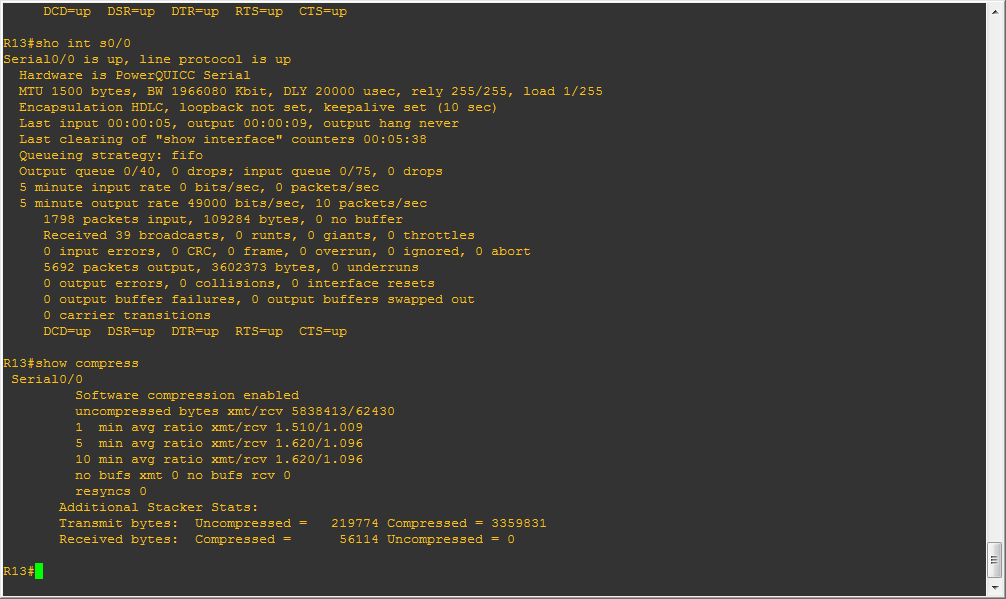
Stacker Compression!
And you can see I’m getting about 1.5:1 . Â Not bad for a simple setting change.
Serial0/0
Software compression enabled
uncompressed bytes xmt/rcv 8733770/81026
1 min avg ratio xmt/rcv 1.577/1.121
5 min avg ratio xmt/rcv 1.578/1.070
10 min avg ratio xmt/rcv 1.606/1.083
no bufs xmt 0 no bufs rcv 0
resyncs 0
Additional Stacker Stats:
Transmit bytes: Uncompressed = 279855 Compressed = 5124744
Received bytes: Compressed = 72387 Uncompressed = 0
But naturally dynamips is slow for doing what it does. Â And to know that I’m not totally crazy, as this stuff did work before. Â This should also serve as a warning to people new at the fun world of cisco, just because you have a ‘newer’ version of IOS doesn’t mean that feature XYZ is going to work correctly. Â Oh sure the statements may work, but when it comes down to it, it may not work at all, or poorly. Â In case you ever wondered why people hoarde IOS versions this would be why.
Well I’ve been back using GNS3 to simulate some networks professionally. And well, I hit a roadblock of a strange kind.
In my “LAB” I want to have a ESXi host talking to vCenter, and I wanted to setup a custom logging program which logs to MSSQL, and Maybe Oracle. For routing I need Junos and cisco IOS.
Now the problem is that takes a little bit of everything. The Qemu bundled with GNS3 horribly ancient, and my attempt to drop in Qemu 1.6.0 just fails. Also running things like Windows Server 2008r2 and ESXi run best under VMware. The SQL server stuff can be any version, so even NT 4.0/SQL 7 is fine which GNS3’s Qemu can run, but it is kind of slow. Which I know it isn’t fair to compare something like Virtual Box to VMWare.
So ideally the best bet is to tie them all together, and I found a way.
First I’m using VMWare Player version 6.0.1 build-1379776. The people financing this insane project have things like VMWare workstation but I have to download it through them, and their link is insanely slow, so I’m sticking with the player for now. But I was able to persuade a user to extract “VMware Workstation 10.0.2 build 1744117”, and retrieve two files for me, vmnetcfg.exe and vmnetcfglib.dll. So this way I can setup VMWare network interfaces which GNS3 can then latch onto with pcap.
The feature was available in earlier versions of VMWare Player, but the needed files were removed in the latest version. However, I found if you have access to a new version of VMware Workstation you can just snag these two files, and run them like this (as administrator):
rundll32.exe vmnetcfglib.dll VMNetUI_ShowStandalone
And now you can setup some networks.
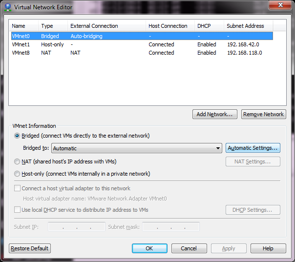
VMware’s default network setup
Now from what I have read online, the best thing to do is leave the default networks alone. However, I found that if I left VMNet0 to the defaults I was unable to join any VM’s to the different networks. So I bind this to my physical Ethernet connection.
Now I want to have various network points to attach VMs onto. The best part that I’ve found is that pcap works on these networks for both listening and injection, so these make better ‘hub’ inspection points IMHO. Also this means you can run emulators that inject libpcap as a method of communication (SIMH, WinUAE, and even my ancient Qemu 0.9.0…)
The big thing is when adding networks, DISABLE DHCP. You can leave the rest where it is, it really doesn’t matter.
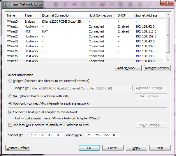
With Networks
As you can see, I’ve now added VMnet2 – VMnet7. This should give me enough user networks for now to play with. I’ve also unchecked the local DHCP service, as I may want to run my own DHCP on an emulated server to make sure DHCP relay works through my virtual network. Once you are happy, you can hit Apply and it will create the network interfaces on your computer.
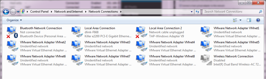
So many networks!
Now going into the control panel and looking at the network adapters (search for “view network connections”), and you will see there are a bunch of these VMWare Network Adapters. The worst part is that they all have full networking enabled, which we don’t want. So, starting with VMnet2, we need to unbind all high-level access.
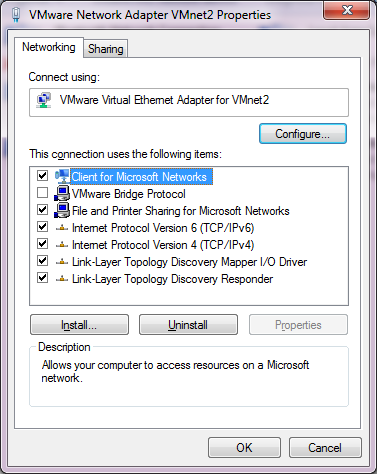
Before
I unbind the ‘Client for Microsoft Networks’, ‘File and Printer Sharing for Microsoft Networks’, and TCP/IP version 4 and version 6. This the Link-Layer topology discovery stuff. I also enabled the VMware Bridge Protocol.
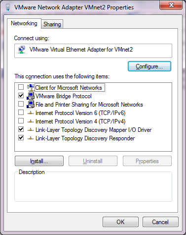
After
Now I just have to repeat this for each of the adapters that we installed, in this case VMNet2 – VMNet7. Remember to leave VMNet0, VMNet1 and VMNet8 alone!
Now for the real fun, you have to reboot for the changes to take effect.
After a reboot, if you run Wireshark, you should now see all the interfaces!
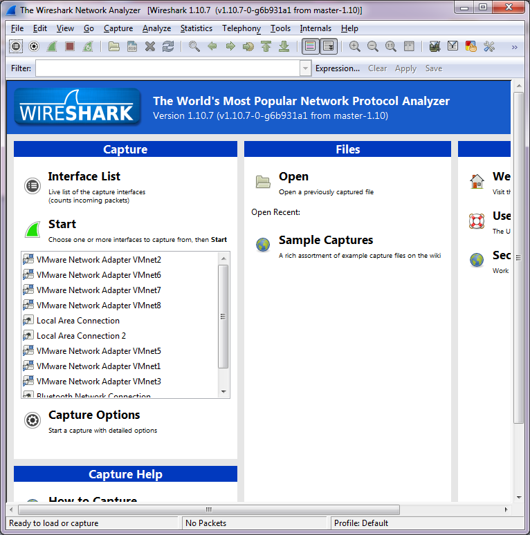
Wireshark with the new interfaces
Ok so far, so good, but let’s tie this mess together!
HHGTTG refrence
So let’s build a network. Our “home” site will have a server network with the ESXi server serving some virtual servers, a user network which will contain our management workstation & a MS-DOS NetWare machine. We will then have a remote network with different machine types, which will be a 4.3BSD VAX, and an Amiga running NetBSD. We’ll also include a Novell Netware 3.12 server. Add in an ‘internet’ router, and we should be good.
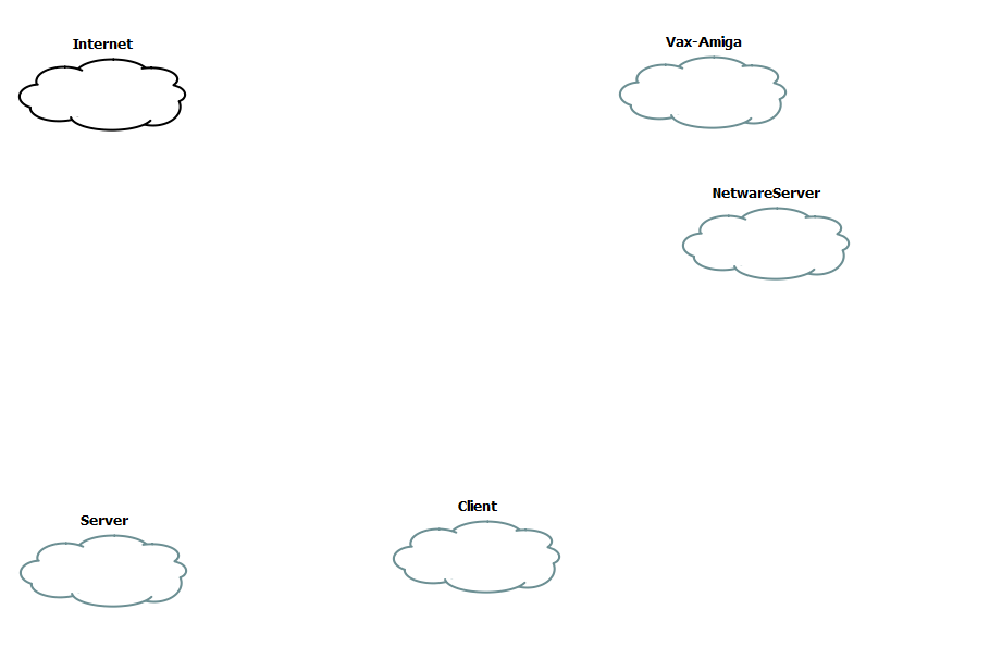
Clouds
The first step is to create some clouds. Each one of these will then be associated with a VMNetwork device.
[table]Network,Device
Server,VMNet2
Vax-Amiga,VMNet3
NetwareServer,VMNet4
Client,VMNet5
Internet,VMNet8[/table]
Now you’ll notice that I’m assigning VMNet8 to the ‘internet’. If you remember the original VMWare table, the VMNet8 device is a ‘NAT’ device. So, we can use that to get to the internet (well anything else the base device can access). Now I’ve gone ahead and added in two cisco routers, a single juniper router and a hub, as the juniper device cannot directly connect to the Internet cloud, but using the hub for the intermediary is ok.
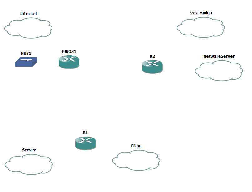
Add in the routers & hub
Now it’s time to add some interfaces to the routers. I’m going to put the C7200-IO-2FE into both R1 & R2, along with a PA-4T+ serial adapter. Because I want to pretend to have a fast internet connection, I’m also going to place a PA-GE interface into R1 in slot 2.
Now we need to bind each cloud to the corresponding VMnet interface.
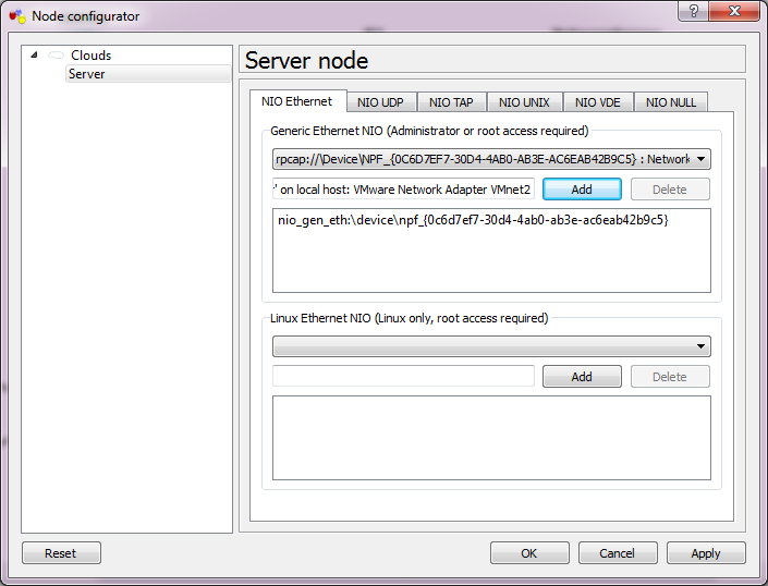
Server Network
Simply double click on the cloud, and select the VMNet interface from the drop-down list, then add it and the interface is now bound. Repeat for each of the clouds.
Now we can connect the interfaces.
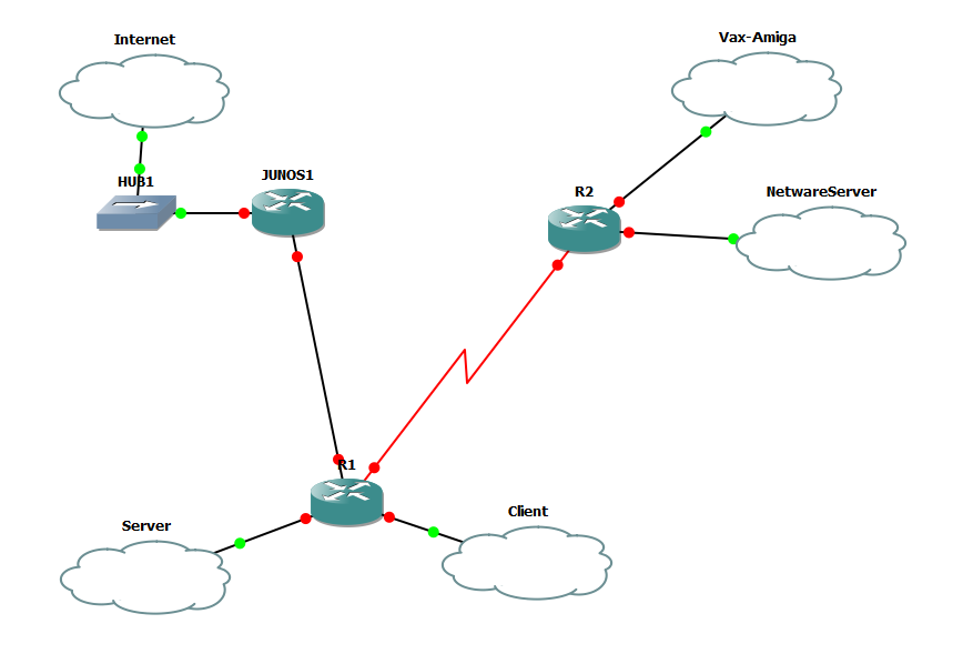
Now with Interfaces
So R1’s FA0/0 is connected to the SERVER cloud, FA0/1 is connected to the CLIENT cloud. Serial 1/0 is connected to R2’s Serial 1/0 interface. the G2/0 interface is connected to Junos1’s e1 interface
R2’s FA0/0 is connected to the VAX-AMIGA cloud, and the FA0/1 is connected to the NETWARESERVER cloud.
Junos1’s e0 is connected to HUB1, which is then connected to the INTERNET cloud.
[table]
NAME,Interface,IPX,IP
Server,VMNet2,,192.168.0.0/24
Vax-Amiga,VMNet3,,192.168.1.0/24
NetwareServer,VMNet4,cab2,
Client,VMNet5,cab3,192.168.2.0/24
Internet,VMNet8,,DHCP
serial,none,cab0,192.168.255.0/30
GigE,none,,192.168.255.4/30
[/table]
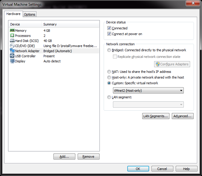
Configure the network interface in VMWare Player
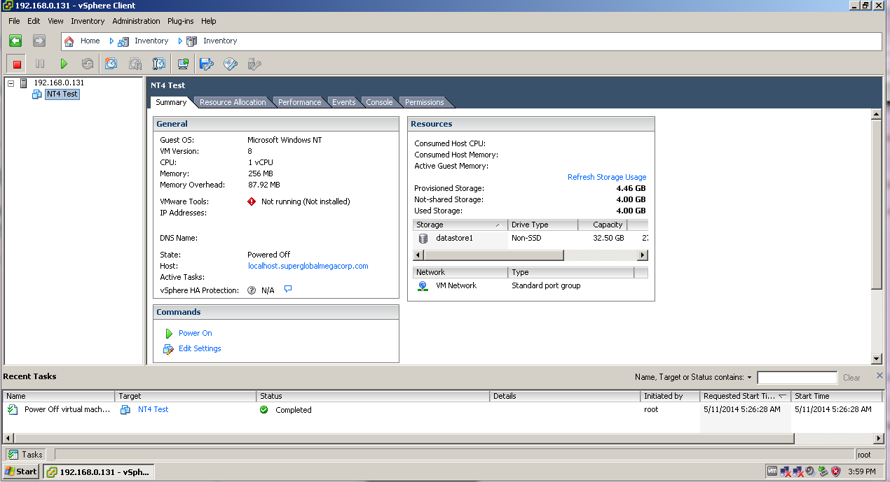
Since I already have an ESXi VM on Player, I’m going to use this for my illustration. All I need to do here is change the existing network from being ‘bridged’ on my native network, to now being on VMnet2, which now places it inside of my GNS3 world. Likewise I take a Windows XP client, and place it on VMnet3.
Now to configure R1 like the following:
[table]
Interface,IP-Address,OK?,Method,Status,Protocol
FastEthernet0/0,192.168.0.1,YES,manual,up,up
FastEthernet0/1,192.168.2.1,YES,manual,up,up
Serial1/0,192.168.255.1,YES,manual,up,up
GigabitEthernet2/0,192.168.255.5,YES,manual,up,up
[/table]
And R2 like the following:
[table]
Interface,IP-Address,OK?,Method,Status,Protocol
FastEthernet0/0,192.168.1.1,YES,manual,up,up
FastEthernet0/1,unassigned,YES,unset,up,up
Serial1/0,192.168.255.2,YES,manual,up,up
[/table]
And now I can connect from my Client PC, the VMware ESXi server!
Connection
This gives me an easy way to ‘view’ into what is going on for my client to connect to the server.
Now some quick EIGRP to get R1 & R2 routing together..
R1:
router eigrp 1
network 192.168.0.0
network 192.168.2.0
network 192.168.255.0 0.0.0.3
no auto-summary
R2:
router eigrp 1
network 192.168.1.0
network 192.168.255.0 0.0.0.3
no auto-summary
And now we can check routs on R2, and see it’s learnt the routes from R1:
192.168.255.0/30 is subnetted, 1 subnets
C 192.168.255.0 is directly connected, Serial1/0
D 192.168.0.0/24 [90/2172416] via 192.168.255.1, 00:15:50, Serial1/0
C 192.168.1.0/24 is directly connected, FastEthernet0/0
D 192.168.2.0/24 [90/2172416] via 192.168.255.1, 00:15:50, Serial1/0
I was a little disappointed though, that Olive can’t do any flow based stuff like security policies or NAT.
So onward with SIMH. I’ve found that I have a LOT of Ethernet interfaces and some things cannot deal with that. I had to make a trivial change to sim_ether.h:
#define ETH_MAX_DEVICE 32 /* maximum ethernet devices */
SIMH had this value hard-coded to 10, and it crashed because I have… 11 interfaces. So, it just took a quick re-compile and now I can see my interfaces!
0 \Device\NPF_{0C6D7EF7-30D4-4AB0-AB3E-AC6EAB42B9C5} (VMware Network AdapterVMnet2)
1 \Device\NPF_{1A17F8DF-DC65-420E-9A7A-3F8D22EC0D12} (VMware Network AdapterVMnet6)
2 \Device\NPF_{5A889C62-8180-4DB5-8FFE-3B6B8B9DFFAF} (VMware Network AdapterVMnet7)
3 \Device\NPF_{A6B89C5C-C28C-424E-B795-F90F97FA0FE7} (VMware Network AdapterVMnet8)
4 \Device\NPF_{21FFD0D4-1B8B-47B7-B0DD-28CD67DF4080} (Local Area Connection)
5 \Device\NPF_{70AA2D26-7B96-42FB-9FA6-8A7386753099} (Local Area Connection 2)
6 \Device\NPF_{98F44EE6-626B-48CB-952D-9C890F44A4A5} (VMware Network AdapterVMnet5)
7 \Device\NPF_{D294A70E-07B3-4CA8-A88D-D6C392696E99} (VMware Network AdapterVMnet1)
8 \Device\NPF_{F746872D-7687-4867-958C-96A62BA5E284} (VMware Network AdapterVMnet3)
9 \Device\NPF_{783262C6-8B95-4F9E-B198-78E2D9B256BB} (Bluetooth Network Connection)
10 \Device\NPF_{D6726593-C290-4821-8D43-D180CF5631BA} (VMware Network AdapterVMnet4)
Wow!
So with SIMH I can now attach to eth8, which maps to VMnet3.
set xu ena
att xu eth8
Easy, right?
And even better, it works!
R2#ping 192.168.1.15
Type escape sequence to abort.
Sending 5, 100-byte ICMP Echos to 192.168.1.15, timeout is 2 seconds:
!!!!!
Success rate is 100 percent (5/5), round-trip min/avg/max = 8/15/28 ms
R2#
And the XP workstation can telnet to it…
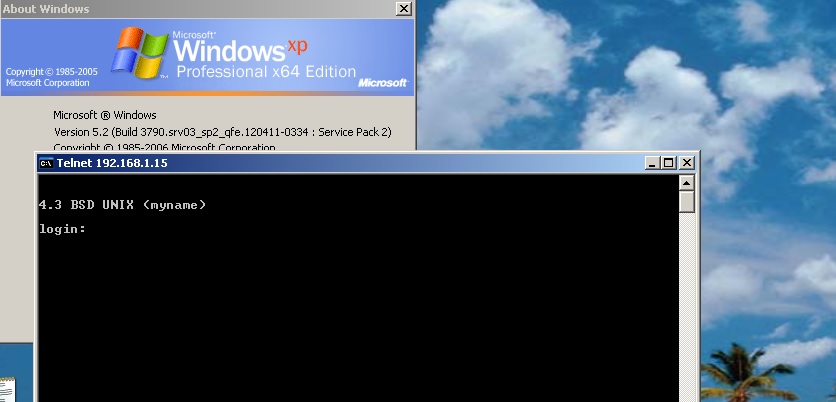
VMWare routed through GNS3
Next I’ll have to add in some NetWare fun. For the heck of it. Good news is that it works!
One caveat I’ve found is that sometimes the ARP response time isn’t so hot, and it seems like everything times out.. So you may want to tweek the default arp age on the cisco side (interface bla/arp timeout 600..?).
Following up my JunOS post, here is a handy script I cooked up to pull the configuration from a Cisco IOS device. Â The one trip up for this stuff is sometimes you can logon to a cisco device, and you can be at the enabled state, you may have to enable, Â and depending on how it’s configured you may have to use an enable password, which may be your password (again) or you may have to use a different password.
So yeah with a bunch of testing around this seems to work well enough for me.
#!/usr/local/bin/expect —
set MYUSER “my_user_name”
set MYPASS “my_password”
set ENPASS “my_enable_password”
set HOST [lindex $argv 0];
set timeout 90
if {$argc!=1} {
puts “Usage is scritpname <ip address>\r”
exit 1
}
#
#
puts “Connecting to $HOST\r”
spawn ssh $HOST -l $MYUSER
# Deal with hosts we’ve never talked to before
# or just logon
#
expect {
“*yes/no*” {send “yes\r” ; exp_continue }
“*assword:” {send “${MYPASS}\r” }
}
set ALREADY 0
expect {
“\r*>” {}
“\r*#” { set ALREADY 1}
“*enied” {exit 1}
“*assword” {exit 1}
}
if { $ALREADY < 1 } {
send “enable\r”
expect “*assword:” {
send “${MYPASS}\r”
expect {
“*enied” {
send “enable\r”
expect “*assword:”
send “${ENPASS}\r”
expect {
“*enied” {
exit 1}
“\r*#” {}
}
}
“\r*#” {}
}
}
}
send “show run\r”
expect {
“ore” {send ” “; exp_continue}
“\r*#” {}
}
#Let’s get out of here
send “q\r”
expect eof
exit 0
This is a little more cleaner than the prior JunOS one, as I’ll keep on improving it.
It works with ASA’s (tested 8.2)and IOS (tested 12.2)
Much like my prior article on Configuring TCP/IP, the process for configuring IPX/SPX on a cisco router is pretty much the same thing.
The first big ‘gottcha’ in the world of IPX is that it supports multiple frame types. Â This winds up leading to all kinds of troubles when various people setup various servers. Â It is inevitable that people pick their own and incompatible frame type. Â The only to ‘fix’ this is for everyone to be on the same type. Â I have heard of people using different frame types for different environments, much like using 802.1q (trunking) to separate various peoples traffic who do not want to see each-others resources. Â But back when IPX was prevalent, people were still using HUBS which mirror all traffic, and primitive layer two switching at best. Â Not to mention with the advent of Netware 4, you could have virtual NIC’s in the server and workstations, and bind to all possible frame types.
Things got messy, and quick.
But I digress, for this example I’m going to use the ‘default’ frame type of ETHERNET_802.2 or SAP is cisco speak. Â Mostly because I don’t feel like fully configuring the MS-DOS client I managed to dig up, and mostly because at this point (2013) I really don’t care what frame type I use.
I’m going to setup the following IPX networks:
WANÂ C0000001
SERVERÂ C0010001
USERÂ C0010002
The first step is to enable the ipx protocol on the router. Â This is done with the ‘ipx routing’ command.
corertr1#config t
Enter configuration commands, one per line. End with CNTL/Z.
corertr1(config)#ipx routing
corertr1(config)#exit
corertr1#
Now the IPX protocol is enabled. Â The next step is to configure the ethernet interfaces. Â This is pretty straightfoward, we put in the network numbers, and assign the correct frame types.
corertr1#config t
Enter configuration commands, one per line. End with CNTL/Z.
corertr1(config)#int eth1/0
corertr1(config-if)#ipx encapsulation SAP
corertr1(config-if)#ipx network c0010001
corertr1(config-if)#exit
corertr1(config)#int eth1/1
corertr1(config-if)#ipx encapsulation SAP
corertr1(config-if)#ipx network c0010002
corertr1(config-if)#exit
corertr1(config)#int fa0/0
corertr1(config-if)#ipx network c0000001
corertr1(config-if)#ipx encapsulation SAP
corertr1(config-if)#exit
corertr1(config)#exit
corertr1#
Now we can quickly check the interfaces that IPX is running on with the ‘show ipx interface brief’ command. Â You should get something like this:
corertr1#show ipx interface brief
Interface IPX Network Encapsulation Status IPX State
FastEthernet0/0 C0000001 SAP up [up]
FastEthernet0/1 unassigned not config’d admin down n/a
Ethernet1/0 C0010001 SAP up [up]
Ethernet1/1 C0010002 SAP up [up]
Ethernet1/2 unassigned not config’d admin down n/a
Ethernet1/3 unassigned not config’d admin down n/a
Ethernet1/4 unassigned not config’d admin down n/a
Ethernet1/5 unassigned not config’d admin down n/a
Ethernet1/6 unassigned not config’d admin down n/a
Ethernet1/7 unassigned not config’d admin down n/a
So far, so good. Â Now the next question is, does the router see the server? Â And what kind of services are available on the network? Â This can be found with the ‘sho ipx servers’ command.
corertr1#sho ipx servers
Codes: S – Static, P – Periodic, E – EIGRP, N – NLSP, H – Holddown, + = detail
U – Per-user static
3 Total IPX Servers
Table ordering is based on routing and server info
Type Name Net Address Port Route Hops Itf
P 4 FPNWDC_NW DEAD0001.0000.0000.0001:0451 2/01 1 Et1/0
P 444 VIRTUALLYFUN!FPNWDC DEAD0001.0000.0000.0001:84C8 2/01 1 Et1/0
P 640 FPNWDC DEAD0001.0000.0000.0001:E885 2/01 1 Et1/0
Everything is looking good! Â As you can see my virtual Netware server (FPNW on NT 4.0) is type 4, and called FPNWDC_NW. Â SAP types 444 and 640 are for Windows NT, with 444 being the NetBIOS Browser/Domain control service.
IPX is a rather chatty protocol, and it is easy for things to go wrong. Â Another fun command is ‘show ipx traffic’ which will let you get some idea of what kind of chat is going on.
corertr1#show ipx traffic
System Traffic for 0.0000.0000.0001 System-Name: corertr1
Time since last clear: never
Rcvd: 149 total, 34 format errors, 0 checksum errors, 0 bad hop count,
100 packets pitched, 29 local destination, 0 multicast
Bcast: 126 received, 64 sent
Sent: 79 generated, 18 forwarded
0 encapsulation failed, 2 no route
SAP: 0 Total SAP requests, 0 Total SAP replies, 3 servers
0 SAP general requests received, 4 sent, 0 ignored, 0 replies
0 SAP Get Nearest Server requests, 0 replies
0 SAP Nearest Name requests, 0 replies
0 SAP General Name requests, 0 replies
18 SAP advertisements received, 15 sent, 0 Throttled
4 SAP flash updates sent, 0 SAP format errors
RIP: 2 RIP requests, 0 ignored, 2 RIP replies, 4 routes
9 RIP advertisements received, 30 sent 0 Throttled
7 RIP flash updates sent, 0 atlr sent
4 RIP general requests sent
0 RIP format errors
Echo: Rcvd 0 requests, 0 replies
Sent 10 requests, 0 replies
0 unknown: 0 no socket, 0 filtered, 0 no helper
0 SAPs throttled, freed NDB len 0
Watchdog:
0 packets received, 0 replies spoofed
Queue lengths:
IPX input: 0, SAP 0, RIP 0, GNS 0
SAP throttling length: 0/(no limit), 0 nets pending lost route reply
Delayed process creation: 0
EIGRP: Total received 0, sent 0
Updates received 0, sent 0
Queries received 0, sent 0
Replies received 0, sent 0
SAPs received 0, sent 0
Trace: Rcvd 0 requests, 0 replies
Sent 0 requests, 0 replies
In this brief guide, I’m not going to even get into all of this, however it is important to know that the router has sent things, and received things back.
Another thing that is different about IPX vs TCP/IP is that each server has it’s own internal network, where the services originate from. Â You can see this with the show ipx route command
corertr1#show ipx route
Codes: C – Connected primary network, c – Connected secondary network
S – Static, F – Floating static, L – Local (internal), W – IPXWAN
R – RIP, E – EIGRP, N – NLSP, X – External, A – Aggregate
s – seconds, u – uses, U – Per-user static/Unknown, H – Hold-down
4 Total IPX routes. Up to 1 parallel paths and 16 hops allowed.
No default route known.
C C0000001 (SAP), Fa0/0
C C0010001 (SAP), Et1/0
C C0010002 (SAP), Et1/1
R DEAD0001 [02/01] via C0010001.5254.0012.3456, 10s, Et1/0
As you can see from the SAP advertisements above, and the route here, the server is configured for it’s internal network to be DEAD0001.  The router picked up the advertisement from C0010001.5254.0012.3456, which breaks down as c0010001 being the network the server is on (the server network), and 5254.0012.3456 being the MAC address of the server.
The real test comes from trying to use a client.
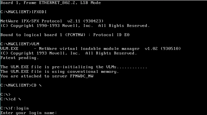
Netware 3.12 client
As you can see, this MS-DOS client attached to the client vlan, can see and interoperate with the virtual NetWare server.
This pretty much covers the basics of getting IPX/SPX working. Â Logically the next thing to do would be to configure routing and get IPX working throughout the WAN. Â But I’m going to save that for a later time.
The more ‘advanced’ topics of IPX involve filtering, as it was a common problem in large networks where you could simply have too many servers, and they would be constantly talking among themselves. Â Another problem is licensing, where some products are licensed in certain areas, and you want those licenses to stay in a geographic area. Â Latency was another issue too, it was insane to say use a SNA server in Japan, to talk to a mainframe in Arizona when you were in Arizona. Â Or if you had a 3rd party, and you only wanted them to connect to a print server, and a single file server, you would setup access-lists on your peer router, much in the same way that we setup firewalls in this fine modern age 😉
So thanks to fakenamegenerator.com I thought I should add some people and setup various workstations around my fake network. With that said, here is my list:
| name | user id | country | PC |
| Hazel B. Forrest | hforrest | USA | MS-DOS |
| James M. White | jwhite | USA | Windows 3.1 |
| Russell I. Ward | rward | USA | |
| Valerie H. Shimp | vshimp | USA | |
| Vera H. Williams | vwilliams | USA | |
| Marie J. Brown | mbrown | UK | Windows 95 |
| Jason S. Seymore | jseymore | UK | |
| Mingmei Hao | mhao | HK | OS/2 1.21 |
| Guang Huang | ghuang | HK | |
| Wit Pawlak | wpawlak | PL | WindowsNT 4.0 |
| Fabio Napolitani | fnapolitani | IT |
Which is enough to get me started in creating some users.
For starters I thought it would be fun to make up some applications the users can ‘use’ on this fine network. Â A mainframe is a must, however Hercules doesn’t emulate SNA networks. Â Which is kind of sad. Â I did find an evaluation copy of Microsoft SNA Server 2.11 which runs great on NT 3.5 and higher. Â However it is limited to two sessions, but to be honest back when I used a mainframe for work, Microsoft SNA server was honestly the best thing out there. Â I had a NT 4.0 / SNA 2.11 install that had uptime in YEARS, while the later SNA 3.0, 4.0 and HIS stuff constantly had issues.
For email, I thought I’d go with something positively ancient, Microsoft Mail 2.1c.
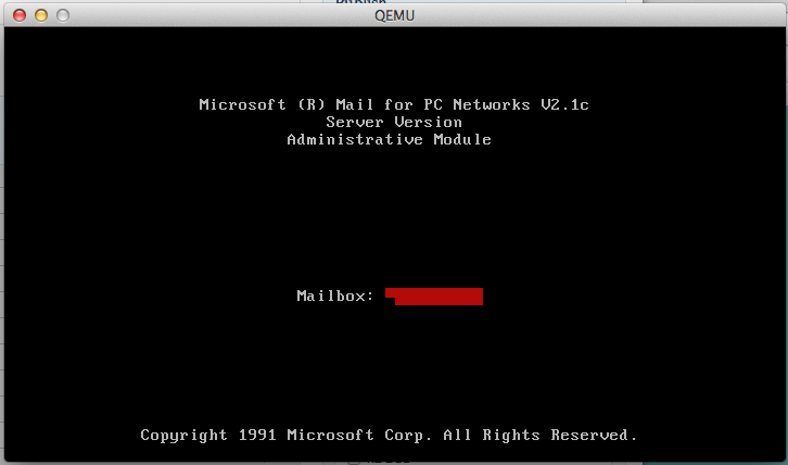
Microsoft Mail
Back then, email programs were just flat databases that allowed multiple people to read/write/lock files over a network. It is very reminisce of how BBS multiuser doors & databases work. MS Mail 2.1 includes clients for MS-DOS, Windows 3.X while the later 3.5 version included an OS/2 client that used the WLO libraries, which was a port of Windows 3.0 to run on top of OS/2. Â I kind of covered this thing back here, although it was mostly geared to version 3.5, it basically is the same thing.
I’ve been using a Windows NT 4.0 server loaded up with the FPNW, so it looks like a NetWare server. Â Although Netware 3.12 runs on Qemu 0.90, it is lacking UDP bridge support to communicate with dynagen/dynamips. Â I did find out that VirtualBOX does support the UDP bridge, and will even run Netware 3.12, HOWEVER, after transferring a few megabytes, the server will stop responding, and dynamips will crash. Â Not a very satisfactory solution. Â So until I get around to backporting the UDP code, this NT server will serve as my virtual ‘Netware’ server for the time being.
I was also going to run SQL Server 4.21a on WindowsNT, however I did come across SQL Server for OS/2, so I will be installing an OS/2 machine complete with Lan Manager, and SQL Server. Â The only downside is that LanManager relies on the non-routable NetBEUI protocol. Â However it is just as awkward as bridging mainframe traffic, so I guess that is a hidden plus. While a program to talk to the database outside of the old isql stuff would be nice, I suspect that doing anything beyond Visual Basic + ODBC would take too much time, and honestly not really be all that worth it.
Also looking at this fine program, Stomper, which lets your share a modem over a network, I thought it would be fun to try in combination with rlfossil for some BBSing adventures.  Back before the internet was open to commercial ISPs it wasn’t uncommon for corporations to pool modems over a LAN.  Remote access was typically handled with specialized hardware appliances like the Shiva LanRover. As far as I know, the only real dialup server that Microsoft had was incorporated with Windows NT 3.5.
Once I get this networking operating correctly, then I’ll start to add things like redundancy via HSRP in my core site, backup network connections, an internet connection, upgrade to an exchange server, some BGP peering, and a VPN server.
Just like the real world!