So, Ive been playing around with emulators, and for some reason I think it’d be awesome to have a real one. Â So I check ebay, and yeah there is a few, Altered Beast, Shinobi, and even an Outrun, and a couple of Hang Ons! Â Wow this is so cool, then I check the prices, and shipping and yeah it’s REAL expensive, REAL quick. Â And even back when I did own an Altered Beast board, I never got it hooked up as it was ‘too hard’.
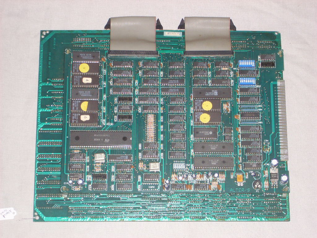
So, I’m about to give up on the whole thing, then I spot this Altered Beast board, for sale for a mere €50!  And the shipping isn’t too insane either!  But looking at the PCB board in the picture, and I can tell something is not quite right:
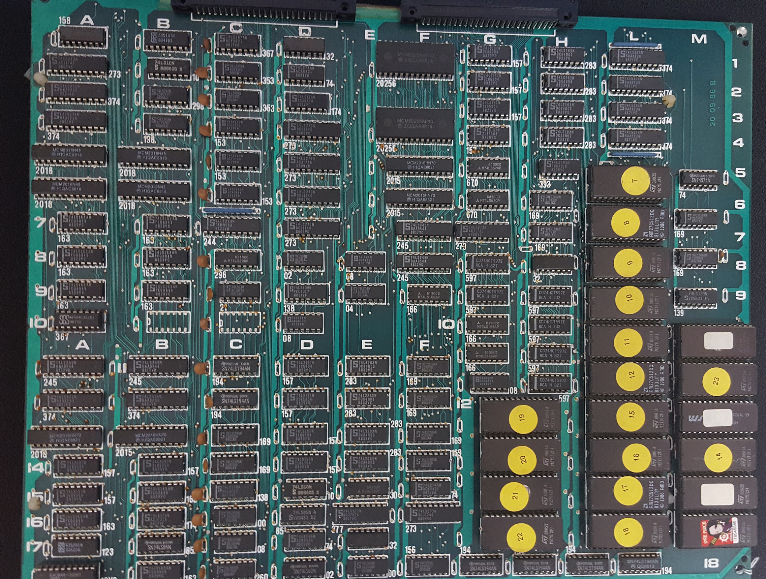
Now for those who don’t know, this clearly is not a System16 board. Â However it certainly does have a 68000, and z80 processor! Â Could this be some 2nd tier manufacturing job? Or perhaps it’s one of these infamous bootleg boards?
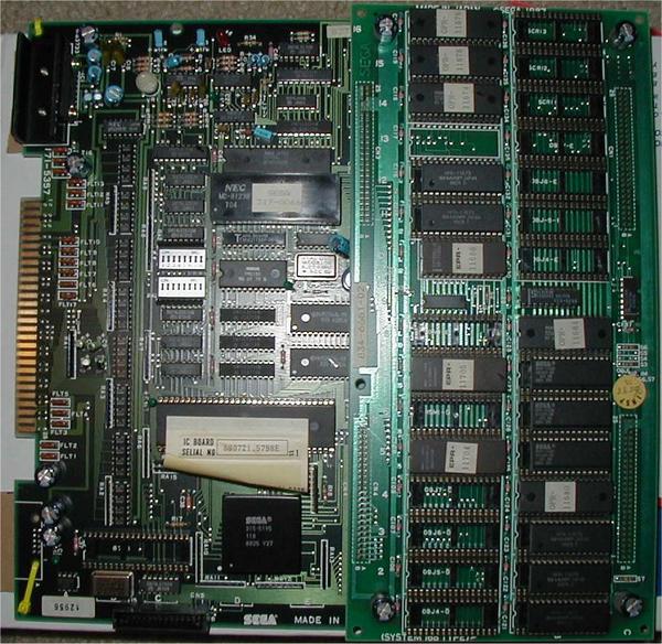
For comparison, here is a real SEGA System16 board
As you can see, they really look nothing alike.  Also the other give away is that the far cheaper €50 board is JAMMA compatible.  All the old SEGA boards are not.
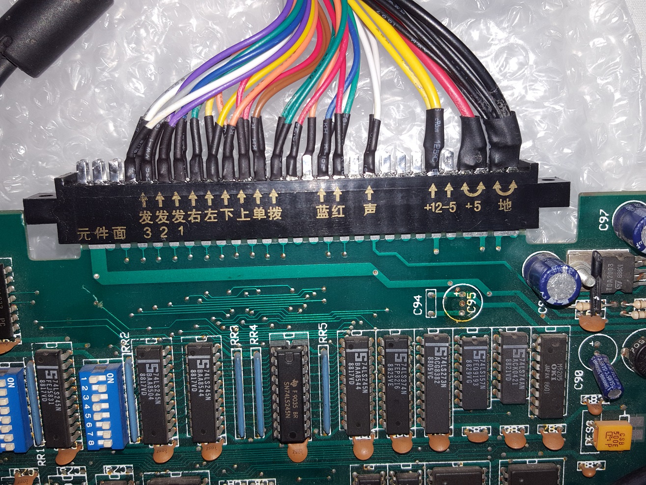
What the heck is JAMMA anyways? Â You see that edge connector? Â That is where you would plug in the power, coin catchers, the player buttons, and the speakers to. Â Even in the old days, recycling cabinets was a thing, and having modular boards was a ‘good thing’. Â But SEGA didn’t want you to swap out their boards with anyone elses, so they used their own system. Â But it’s just a wiring thing, there is nothing digitial locked down, no encryption either (look at HDMI!). Â So you can use an adapter, to interface from SEGA to JAMMA.
Anyways, I went ahead and placed the order.
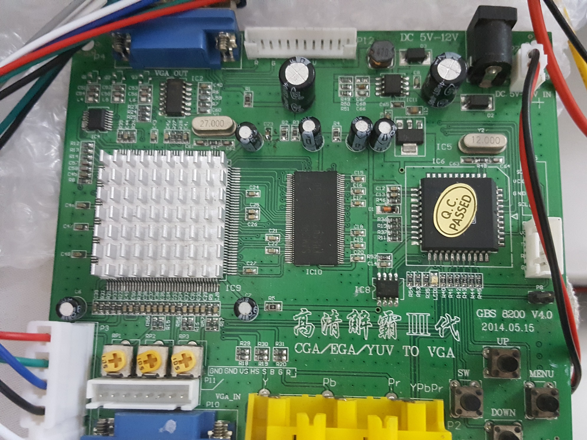
Now doing some more research, and the monitors used in 1980’s arcades were RGB+Sync driven.  Which are ancient, and of course, HEAVY. But a little bit of searching led me to the to the GBS 8200 v4.0.
AKA known as the “GBS8200 CGA/EGA/YUV/RG
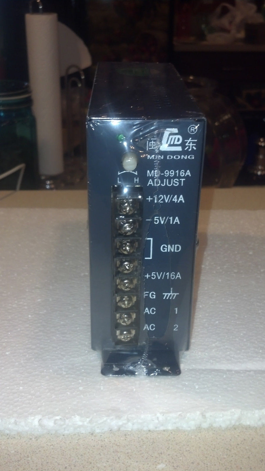
Next up is the power, I decided to get a “JAMMA” power supply. Â A bunch of searching, and this one was the cheapest one I could find, and again shipping wasn’t too bad, but not great either. Â The supply was again around $20 USD, but shipping was $15. OUCH.
I figured having the ability to screw in would be a ‘good thing’.
Naturally, I need the cables to wire this mess together, so I ordered a “JAMMA Cabinet Wire Wiring Harness Loom” for about $15 USD. Â Naturally mine is all in Chinese since I went cheap. Â But it’s OK, I have a multi meter so I can test continuity.
Finally I saw a QANBA N1 arcade style joystick in a local mall for $230 HKD.  That is less than HALF the price of the ones I see online in the USA, Europe, or Canada.  So at least that is nice.  Now with all the parts, I just have to wait for the board to arrive.  And wait, and wait.  Nothing updated on ebay, then suddenly I check a few days later, as it’s been two weeks by this point, and it turns out that it’s been sitting in the post office in Hong Kong for a week!  If only they let me know…  SF Express, and FedEx have come without issues.  Oh well, now I have the board!
I can now finally flip it over to reveal:
It’s all 74L TTL logic chips, EEPROMS, and some PALs as well. Â There are NO custom SEGA chips at all. Â If anything this is what is inside of the SEGA ASIC’s on the System16 board. Â Whoa.
Ok, so this is certainly a bootleg board. Â A quick search of MAME shows that they have a Datsu ROMset, so maybe this is one? Â Nothing on the boards say Datsu, however it does say ALTER/S, and it shows being QA’d on 11/11/88.
Now it’s time to cable this thing up!
But first JAMMA boards are typically key’d so you cant put the adapter in backwards. Â There is no key on this board, so I need to check the voltages to make sure I don’t flip it backwards.
JAMMA Standard Pinout
| ** | Solder Side | Parts Side | ** | ||
|---|---|---|---|---|---|
|
|
|
|
|
||
| GND | A | 1 | GND | ||
| GND | B | 2 | GND | ||
| +5v | C | 3 | +5v | ||
| +5v | D | 4 | +5v | ||
| -5v | E | 5 | -5v | ||
| +12v | F | 6 | +12v | ||
| Key, No Pin | H | 7 | Key, No Pin | ||
| Coin Counter 2 | J | 8 | Coin Counter 1 | ||
| Coin Lockout | K | 9 | Coin Lockout | ||
| Speaker (-) | L | 10 | Speaker (+) | ||
| NC | M | 11 | NC | ||
| Video Analog Green | N | 12 | Video Analog Red | ||
| Video Composite Sync | P | 13 | Video Analog Blue | ||
| Service Switch | R | 14 | Video Ground | ||
| Tilt/Slam | S | 15 | Test | ||
| Coin B | T | 16 | Coin A | ||
| Player 2 Start | U | 17 | Player 1 Start | ||
| Player 2 X-Dir | Player 2 Up | V | 18 | Player 1 Up | Player 1 X-Dir |
| Player 2 Y-Dir | Player 2 Down | W | 19 | Player 1 Down | Player 1 Y-Dir |
| Player 2 X-Clk | Player 2 Left | X | 20 | Player 1 Left | Player 1 X-Clk |
| Player 2 Y-Clk | Player 2 Right | Y | 21 | Player 1 Right | Player 1 Y-Clk |
| Player 2 Button 1 | Z | 22 | Player 1 Button 1 | ||
| Player 2 Button 2 | a | 23 | Player 1 Button 2 | ||
| Player 2 Button 3 | b | 24 | Player 1 Button 3 | ||
| 1 Player 2 Button 4 | NC | c | 25 | NC | Player 1 Button 4 1 |
| 1 Player 2 Button 5 | NC | d | 26 | NC | Player 1 Button 5 1 |
| 2 Player 2 Button 6 | GND | e | 27 | GND | Player 1 Button 6 2 |
| GND | f | 28 | GND | ||
This is the standard pinnout of a JAMMA harness. Importantly you can see it’s Ground than +5v. Â So looking at the 68000 processor to check it’s pinnout:
 |
 |
 |
 |
 |
||||
| D4 |  |
1 |
 |
64 |  |
D5 | ||
| D3 |  |
2 | 63 |  |
D6 | |||
| D2 |  |
3 | 62 |  |
D7 | |||
| D1 |  |
4 | 61 |  |
D8 | |||
| D0 |  |
5 | 60 |  |
D9 | |||
| AS |  |
6 | 59 |  |
D10 | |||
| UDS |  |
7 | 58 |  |
D11 | |||
| LDS |  |
8 | 57 |  |
D12 | |||
| R/W |  |
9 | 56 |  |
D13 | |||
| DTACK |  |
10 | 55 |  |
D14 | |||
| BG |  |
11 | 54 |  |
D15 | |||
| BGACK |  |
12 | 53 |  |
GND | |||
| BR |  |
13 | 52 |  |
A23 | |||
| VCC |  |
14 | 51 |  |
A22 | |||
| CLK |  |
15 | 50 |  |
A21 | |||
| GND |  |
16 | 49 |  |
VCC | |||
| HALT |  |
17 | 48 |  |
A20 | |||
| Reset |  |
18 | 47 |  |
A19 | |||
| VMA |  |
19 | 46 |  |
A18 | |||
| E |  |
20 | 45 |  |
A17 | |||
| VPA |  |
21 | 44 |  |
A16 | |||
| BERR |  |
22 | 43 |  |
A15 | |||
| IPL2 |  |
23 | 42 |  |
A14 | |||
| IPL1 |  |
24 | 41 |  |
A13 | |||
| IPL0 |  |
25 | 40 |  |
A12 | |||
| FC2 |  |
26 | 39 |  |
A11 | |||
| FC1 |  |
27 | 38 |  |
A10 | |||
| FC0 |  |
28 | 37 |  |
A9 | |||
| A1 |  |
29 | 36 |  |
A8 | |||
| A2 |  |
30 | 35 |  |
A7 | |||
| A3 |  |
31 | 34 |  |
A6 | |||
| A4 |  |
32 | 33 |  |
A5 | |||
 |
 |
 |
 |
 |
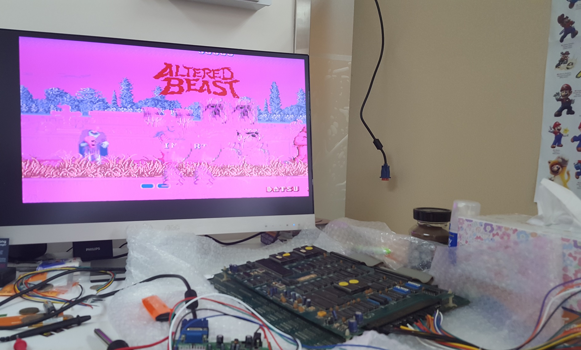
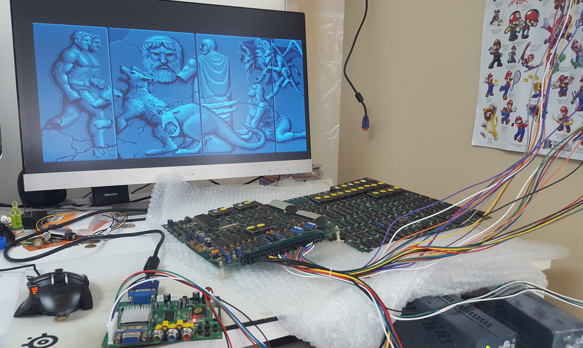
From there, it was a matter of connecting up the power supply, adding in the power to the video board, connecting the RGBS connector, and powering it up. Â It was very cool to get a glimpse of Altered Beast!
And hello, it is a Datsu board.  I’ve tried to google about these boards, and all that I could find out is that they seemed to be popular in Italy.  They may have been made in Korea.  There was another variation called ‘Mutant Warrior/Super Warrior‘.  There was some posts about it in an Italian game forum mameitalia.net, and arcadeitalia.net . Google translate works fine enough to read, but they were in smaller places that couldn’t afford mainstream games, so enter the bootlegs.  And this makes sense, as the board I got was from rural France.
I maybe had a picture for 20 seconds, it was frozen, then the screen went black. Â I power cycled, to nothing. Â I tried it again to a green screen. Â And again to a green screen. Â At this point I think it’s died. Â I let it rest for a few minutes, and try again. Â Nothing. Â I leave it powered up, and feel the processor, and it’s warm. Â It’s doing something, so I think. Â So I start to play with the video board, and as I change resolutions, I get an image!.. then it disappears. Â Power cycling, and changing resolutions occasionally gives me an image. Â I look more closely at the CPU board, and notice that it has 4 standoffs placed on each corner. Â There is nothing in the middle, and over the past 28 years the board is sagging.
In order to fix the sag, I decouple the two boards, and spread them out. Â I try it again, and it doesn’t show me anything. Eventually I play with all the video board settings, and manually set it to the RGBS input, and then the image stays! Â The board is running. Â I tweek some of the settings, and the pink goes away, and now it looks correct!
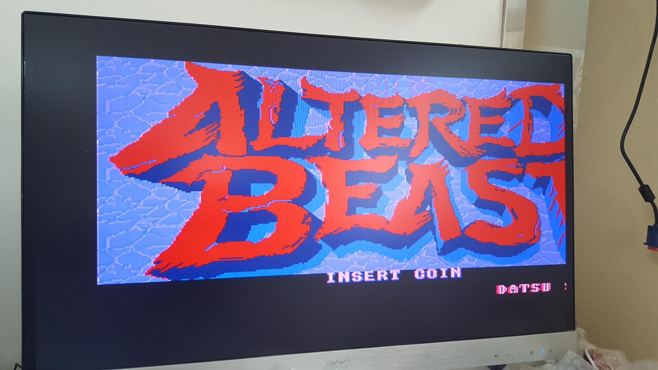
And even the intro animation is OK
OK, now it’s time to turn it off, and wire up the joystick.
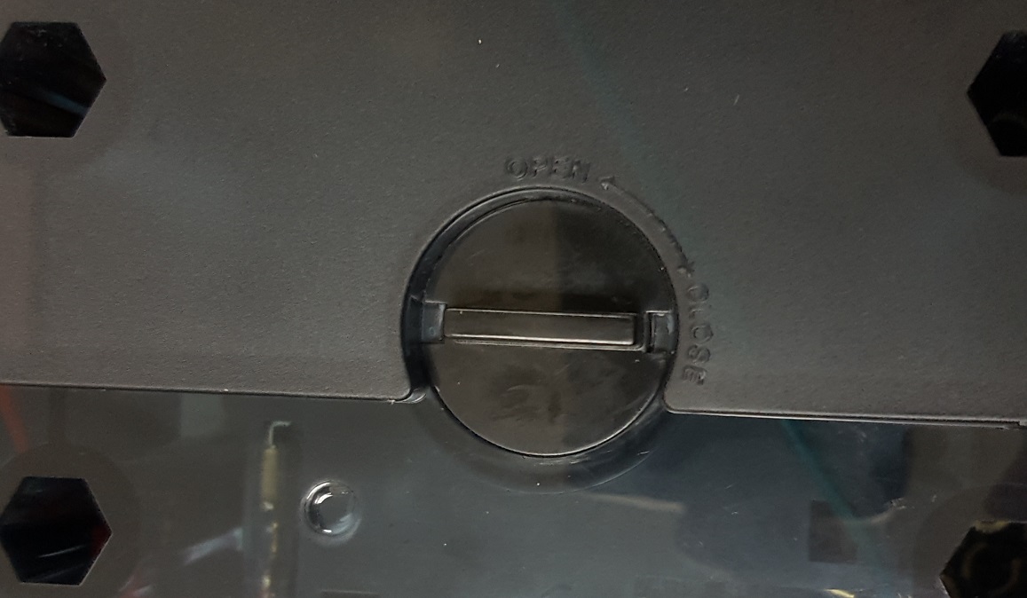
The first step is to remove the joystick ball, and on the QANBA N1 you first flip it upside down, and remove the little cover.
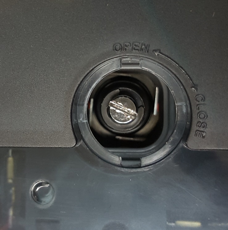
to reveal the screwdriver slot to let you hold the stick in place as you unscrew the ball.
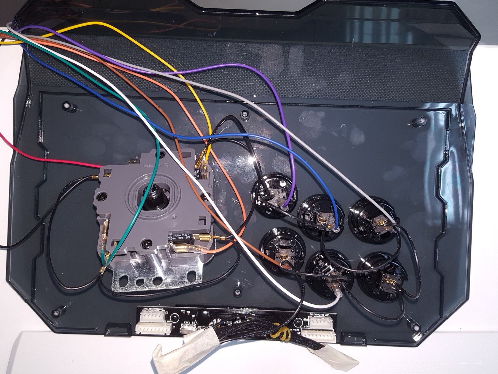
Now it pops off, and it’s really easy to remove the USB interface cables, and drag in the JAMMA cables. Â Again use a tester to tone out what goes where. DO NOT FOLLOW MY COLORING GUIDE. Â I’m pretty sure there is no colour standard, so just because mine is like this, yours will 99.9999% not be. Â The only common thing is that each of these buttons needs a ground.
My harness has a common ground for P1 and P2, so I just tapped up the end and tucked it in the joystick body. Â Now with wired up, I can put the joystick back together, and play!
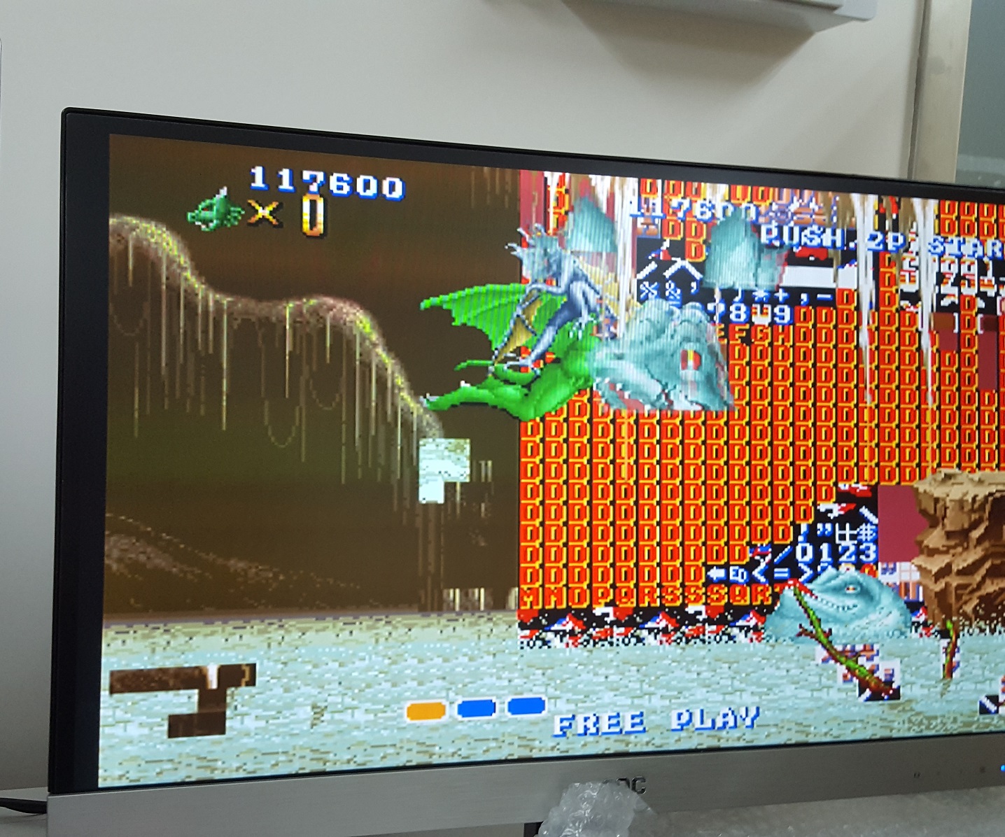
And that is when I could finally see that something was wrong. Â I was doing pretty well, then in the 2nd level I saw this weird thing:
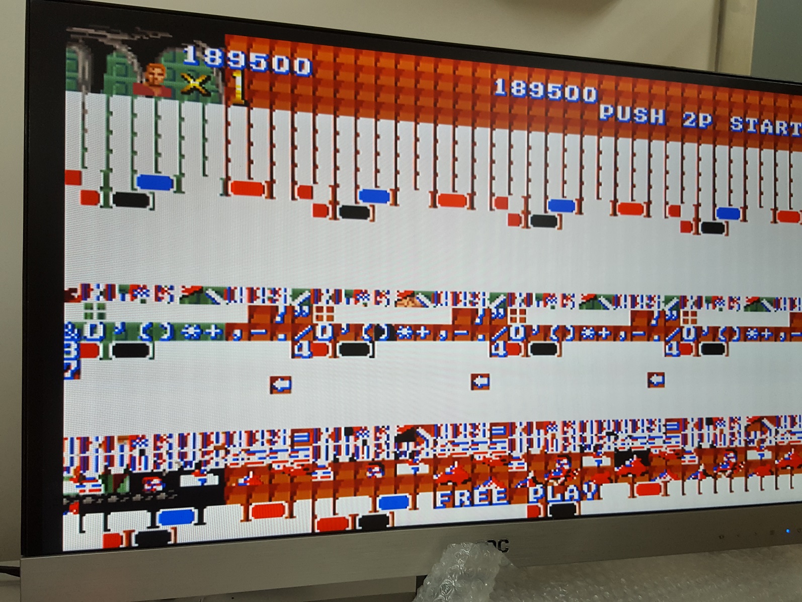
The sprites are working fine, and the gameplay continues. Â But eventually the wall of text effect went from the background to the foreground obscuring game play.
So no doubt something is bad on the board. Â I need to get it looked at, and see about first dumping and checking the EEPROMS. Â Next the RAM on the graphics board, may be suspect as well. Â I think the CPU is fine since it runs OK, I’m just unable to really see pass the wall.
For the heck of it, I went and got some powered speakers, and hooked them up:
And it sounds so different from the SEGA version. Â An inspection of the board shows that there is no YM2151, but rather a pair of YM2203’s and an OKI M5205 for the speech synths.
In retrospect, I probably should have gone with something like the arcade supergun. Â I didn’t know it was a thing unfortunately. Â My solution is more “traditional” , but it works.

That audio…
Yeah, it’s horrible. I wonder what speed the z80 is running at. It sounds 2x faster than it should be.
There’s some graphical issues on Stage 1 also. notice the smoke bugging out
Great job!
Your EPROMs look like 27C512 64kx8. They are UV erasable, you’ll find a window underneath the paper stickers. After time they have been known to lose the stored data (bit rot) but you should be able to re program if you can get dumps from somewhere. You’ll need a UV light source as well as the EPROM programmer.
Yep! I’ve ordered a programmer, and one of the EPROMS didn’t have a sticker, which is why one doesn’t look the same as the others. I suspect this board is the same as the ‘bootleg’ one floating around, but it acts differently, in that the white wolf doesn’t just sit there, and the power spheres also say ‘get it’..
While the GBS-8200 does work it doesn’t do a particularly stella job. At least the one I have seems to treat the progressive video of my Amiga and NeoGeo as interlaced and attempts to de-interlace it. Fortunately it appears to be the firmware limitation and there is some effort to improve it over at http://shmups.system11.org/viewtopic.php?t=52172.
what version do you have? Mine is a 2014.05.15 V4.0 … It looks ‘passible’ to me, the occasional wash and stuff, but the source board is 28 years old, with ancient caps and clearly something broken somewhere….
I’ll have to take a look, it’s the GBS8220 model (only difference is dual VGA output), but I think it was Version 4 too.
I got this board as well. I was wondering if could be a way to adjust audio..
I’m pretty sure that basically the ROMS are either original for the real board, but the program for the z80 only plays at a different frequency, or the audio chip just isn’t capable of whatever it’s being pushed,or initialized incorrectly.
Either way it’s going to require being re-programmed, although I don’t have a clue off hand which ROM, or really what exactly the problem is.
One thing is cool though, the lack of SEGA ASICs shows that basically that giant board is a reversed system 16 graphics chip.
Also the sound chips are totally different, meaning that they had ripped this sound setup from somewhere else, and repurposed it.
I guess they don’t QA too much since yours does the same horrible sound as mine.